Advertorial
Energy Storage Devices: A Battery Testing overview
Fortsetzung des Artikels von Teil 4
Impedance Measurement of Cells
The battery impedance of cells is a key measurement taken during the formation and aging stages. All batteries experience a reduction in performance with cycling. This can be due to the degradation of one or more components or interfaces. There are different methodologies that can be applied, from electrochemical impedance spectroscopy (EIS) to direct diagnostic measurements.
EIS is a non-destructive technique that provides a considerable amount of information in a relatively short time span while preserving the integrity of the battery. To conduct this test, a small AC signal is applied over a wide frequency range and the response is measured. Measurement methodologies involving a span on frequencies are applied to individual cells, but they aren’t applicable for larger sizes and larger operating power modules. In the automotive battery management system (BMS) space, the test is carried out on multi-cell batteries of varying capacities and mismatched cells have to be carefully tracked. Cell mismatch can occur due to battery overcharge, discharge shorts, or simply because of aging.
The Consumer Portable Battery-Operated Electronics: testing needs
What about the testing needs in the market of IoT, medical wearables, and smart home devices?
Embedded devices used for IoT applications are strictly connected to the battery choice, since this impacts the expected lifetime of the device. Batteries needs to be sized to support device workloads for a long period of time. The battery market for IoT relates to small (also “micro”) batteries with thin, flexible, and sometimes unconventional form factor.
When choosing the right battery for their specific application, designers have to consider multiple parameters, including:
- Battery type and declared specs
- Operating temperature range and storage conditions
- Potential energy losses and circuitry leakage
- Application requested ranges and power consumption profile
Let’s focus on the last bullet for a second. Designers need to be aware of the power consumption profile and precisely control the schedule of each executed task by any of the device units (processors, transmitters, etc.). IoT device workloads are sequences of tasks periodically launched in execution with short-duty cycles.
The rate of discharge is strictly dependent on this power schedule, and the intensity, duration, and frequency of these “power usage” pulses. Also, it’s important to control the voltage range of the application, and be aware of the maximum, nominal, and cut off voltage for each subcomponent to correctly operate it.
Based on all the aforementioned considerations, an embedded designer needs to perform:
- A dynamic model battery simulation
- A dynamic current charge / discharge testing (with pulsing sink capability)

The typical test bench will include:
- A basic oscilloscope operating at max 500MHz (typically lower) like the Tektronix TBS2000B or MDO 3 series
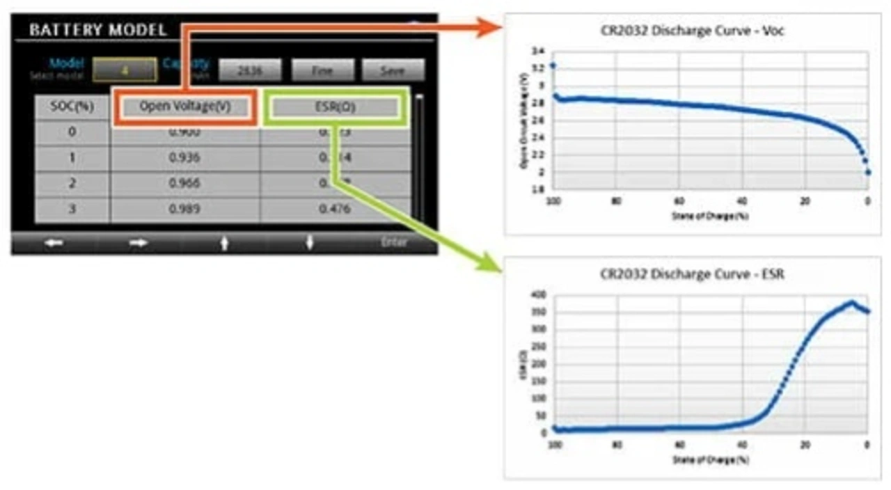
- A multi-channel DC power supply with battery simulation capability (generally linear) like the Keithley 2230 model
- An electronic load, possibly programmable, like that offered by Keithley SMUs
- A DMM with sufficient resolution (DMM6500 when 6 ½ digits is sufficient or for low-power consumption applications, the DMM7510 is recommended to step up to 7 ½ digits)
- An instrument data control software environment (typically PC-based) like Kickstart.
Voltages in this application space do not exceed 10V - 15V max, but current sink in some power-hungry conditions can reach a few Amps (3-4A).
Keithley battery simulators span from the solid 2306 series for production to the 2281S bench solution.
- Energy Storage Devices: A Battery Testing overview
- Li-Ion Batteries Manufacturing: a quick look into production
- Cell-level Assembly, Stacking, Tab Welding, Filling
- Internal Resistance and OCV Measurements
- Impedance Measurement of Cells


