MOST Physical Layer
Glass Fiber Connectivity for Automotive Networks
Fortsetzung des Artikels von Teil 3
Connector proposal

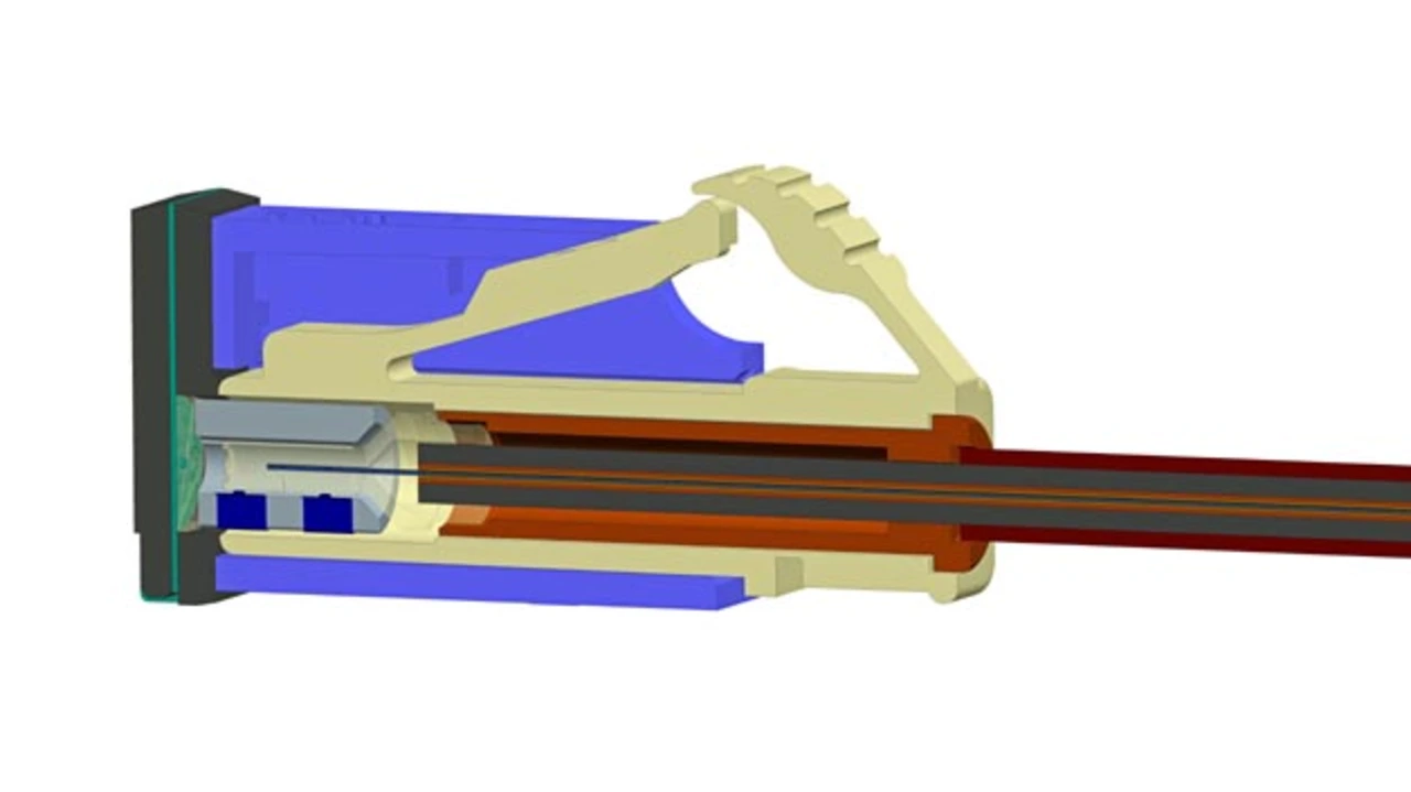
To be robust enough for automotive environmental conditions, the glass fiber(s) end faces are not in contact with each other within an inline connector. The fiber end is terminated with a plastic molded ferrule including a lens feature to achieve sufficient insertion loss performance while not coming into physical contact. This lens allows for an expanded and collimated (almost parallel) beam characteristic at the coupling interfaces (Figure 2). The lenses in this concept are designed and calculated for a collimated beam diameter of approximately 250 µm. With this collimated beam diameter the attenuation risk due to dust particles on the optical interface surfaces is reduced significantly in comparison to a 50/62.5 µm fiber core diameter using butt coupling in the connector. In order to achieve low coupling loss of optical power within a connector, tight control on the alignment of all optical elements within the interface is a key factor.
- Glass Fiber Connectivity for Automotive Networks
- High data rates are possible
- Glass fiber and cable concept for automotive application
- Connector proposal
- The fiber and cable termination process proposal
- Concept discussion: Expanded beam versus physical contact
- Recommendations
- The authors