Leistungsfaktorkorrektur

PFC- und DC/DC-Wandler in Einem

11. Mai 2011, 17:42 Uhr | Von Albert Chen und Alfred Hesener
Diesen Artikel anhören

Fortsetzung des Artikels von Teil 2

Schaltungsbeispiel
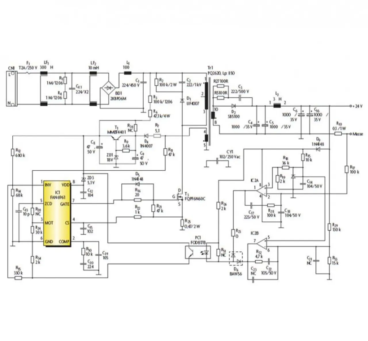
Vollständige Schaltung eines einstufigen PFC-Netzteils zum Speisen von LEDs mit dem Controller FAN6961.
Bild 4. Die vollständige Schaltung eines einstufigen PFC-Netzteils zum Speisen von LEDs mit dem Controller FAN6961.
© Fairchild

Entsprechend den Vorbemerkungen folgt nun die Berechnung eines einstufigen PFC-Schaltnetzteils für eine 30-W-LED-Beleuchtung mit folgenden Spezifikationen:

- Eingangsspannung: 90 bis 264 V(AC)
- Netzfrequenz: 50 Hz / 60 Hz
- Ausgangspannung: 25 V(DC)
- Ausgangsstrom: 1,2 A
- Ausgangsspannungswelligkeit: 1 V

Einige Parameter sollten vor dem Entwurf des Transformators berechnet und bestimmt werden. Zuerst müssen einige anfängliche Parameter festgelegt werden:

- Minimale Schaltfrequenz: 35 kHz
- Reflektierte Spannung UR: 140 V
- Wirkungsgrad: 85 %

Dann erfolgen einige vorläufige Berechnungen:

Eingangsleistung:

«math xmlns=¨http://www.w3.org/1998/Math/MathML¨»«mo»(«/mo»«mn»15«/mn»«mo»)«/mo»«mo»§nbsp;«/mo»«msub»«mi»P«/mi»«mi»E«/mi»«/msub»«mo»=«/mo»«mfrac»«msub»«mi»P«/mi»«mi»A«/mi»«/msub»«mi»§#951;«/mi»«/mfrac»«mo»=«/mo»«mfrac»«mrow»«mn»24«/mn»«mi»V«/mi»«mo»§#183;«/mo»«mn»1«/mn»«mo»,«/mo»«mn»25«/mn»«mi»A«/mi»«/mrow»«mrow»«mn»0«/mn»«mo»,«/mo»«mn»85«/mn»«/mrow»«/mfrac»«mo»=«/mo»«mn»25«/mn»«mo»,«/mo»«mn»3«/mn»«mi»W«/mi»«/math»

Minimaler K-Wert:

«math xmlns=¨http://www.w3.org/1998/Math/MathML¨»«mo»(«/mo»«mn»16«/mn»«mo»)«/mo»«mo»§nbsp;«/mo»«msub»«mi»K«/mi»«mi»min«/mi»«/msub»«mo»=«/mo»«mfrac»«mrow»«msqrt»«mn»2«/mn»«/msqrt»«mo»§#183;«/mo»«msub»«mi»U«/mi»«mrow»«mi»E«/mi»«mo»(«/mo»«mi»min«/mi»«mo»)«/mo»«/mrow»«/msub»«/mrow»«msub»«mi»U«/mi»«mi»R«/mi»«/msub»«/mfrac»«mo»=«/mo»«mfrac»«mrow»«mn»1«/mn»«mo»,«/mo»«mn»414«/mn»«mo»§#183;«/mo»«mn»90«/mn»«mi»V«/mi»«/mrow»«mrow»«mn»140«/mn»«mi»V«/mi»«/mrow»«/mfrac»«mo»=«/mo»«mn»0«/mn»«mo»,«/mo»«mn»91«/mn»«/math»

Maximaler Spitzenstrom auf der Primärseite:

«math xmlns=¨http://www.w3.org/1998/Math/MathML¨»«mo»(«/mo»«mn»17«/mn»«mo»)«/mo»«mo»§nbsp;«/mo»«msub»«mi»§#238;«/mi»«mrow»«mi»P«/mi»«mo»(«/mo»«mi»max«/mi»«mo»)«/mo»«/mrow»«/msub»«mo»=«/mo»«mfrac»«mrow»«msqrt»«mn»2«/mn»«/msqrt»«mo»§#183;«/mo»«msub»«mi»P«/mi»«mi»E«/mi»«/msub»«/mrow»«mrow»«msub»«mi»U«/mi»«mi»E«/mi»«/msub»«mo»§#183;«/mo»«mi»F«/mi»«mo»(«/mo»«mi»K«/mi»«mo»)«/mo»«/mrow»«/mfrac»«mo»=«/mo»«mfrac»«mrow»«mn»1«/mn»«mo»,«/mo»«mn»414«/mn»«mo»§#183;«/mo»«mn»35«/mn»«mo»,«/mo»«mn»3«/mn»«mi»W«/mi»«/mrow»«mrow»«mn»90«/mn»«mi»V«/mi»«mo»§#183;«/mo»«mfrac»«mrow»«mn»0«/mn»«mo»,«/mo»«mn»5«/mn»«/mrow»«mrow»«mn»1«/mn»«mo»+«/mo»«mn»0«/mn»«mo»,«/mo»«mn»8«/mn»«mo»§#183;«/mo»«mn»0«/mn»«mo»,«/mo»«mn»91«/mn»«/mrow»«/mfrac»«/mrow»«/mfrac»«mo»=«/mo»«mn»1«/mn»«mo»,«/mo»«mn»92«/mn»«mi»A«/mi»«/math»

Maximaler Effektivstrom auf der Primärseite:

«math xmlns=¨http://www.w3.org/1998/Math/MathML¨»«mo»(«/mo»«mn»18«/mn»«mo»)«/mo»«mo»§nbsp;«/mo»«msub»«mi»I«/mi»«mrow»«mi»P«/mi»«mo»(«/mo»«mi»max«/mi»«mo»)«/mo»«/mrow»«/msub»«mo»=«/mo»«msqrt»«mrow»«mfrac»«mn»1«/mn»«mn»3«/mn»«/mfrac»«mo»§#183;«/mo»«msub»«msup»«mi»§#238;«/mi»«mn»2«/mn»«/msup»«mrow»«mi»P«/mi»«mo»(«/mo»«mi»max«/mi»«mo»)«/mo»«/mrow»«/msub»«mo»§#183;«/mo»«mi»F«/mi»«mo»(«/mo»«mi»K«/mi»«mo»)«/mo»«/mrow»«/msqrt»«mo»=«/mo»«msqrt»«mrow»«mfrac»«mrow»«mn»1«/mn»«mo»,«/mo»«mn»92«/mn»«mi»A«/mi»«/mrow»«mn»3«/mn»«/mfrac»«mo»§#183;«/mo»«mfrac»«mrow»«mn»0«/mn»«mo»,«/mo»«mn»5«/mn»«/mrow»«mrow»«mn»1«/mn»«mo»+«/mo»«mn»0«/mn»«mo»,«/mo»«mn»8«/mn»«mo»§#183;«/mo»«mn»0«/mn»«mo»,«/mo»«mn»91«/mn»«/mrow»«/mfrac»«/mrow»«/msqrt»«mo»=«/mo»«mn»0«/mn»«mo»,«/mo»«mn»596«/mn»«mi»A«/mi»«/math»

Erst jetzt lässt sich der Transformator dimensionieren.

Magnetisierungsinduktivität auf der Primärseite:

«math xmlns=¨http://www.w3.org/1998/Math/MathML¨»«mo»(«/mo»«mn»19«/mn»«mo»)«/mo»«mo»§nbsp;«/mo»«msub»«mi»L«/mi»«mi»m«/mi»«/msub»«mo»§lt;«/mo»«mfrac»«mrow»«msqrt»«mn»2«/mn»«/msqrt»«mo»§#183;«/mo»«msub»«mi»U«/mi»«mrow»«mi»E«/mi»«mo»(«/mo»«mi»min«/mi»«mo»)«/mo»«/mrow»«/msub»«/mrow»«mrow»«msub»«mi»f«/mi»«mi»S«/mi»«/msub»«mo»§#183;«/mo»«msub»«mi»§#238;«/mi»«mrow»«mi»P«/mi»«mo»(«/mo»«mi»max«/mi»«mo»)«/mo»«/mrow»«/msub»«mo»§#183;«/mo»«mo»(«/mo»«mn»1«/mn»«mo»+«/mo»«msub»«mi»K«/mi»«mi»min«/mi»«/msub»«mo»)«/mo»«/mrow»«/mfrac»«mo»=«/mo»«mfrac»«mrow»«mn»1«/mn»«mo»,«/mo»«mn»414«/mn»«mo»§#183;«/mo»«mn»90«/mn»«mi»V«/mi»«/mrow»«mrow»«mn»35«/mn»«mi»<a href=kHz«/mi»«mo»§#183;«/mo»«mn»1«/mn»«mo»,«/mo»«mn»92«/mn»«mi»A«/mi»«mo»§#183;«/mo»«mo»(«/mo»«mn»1«/mn»«mo»+«/mo»«mn»0«/mn»«mo»,«/mo»«mn»91«/mn»«mo»)«/mo»«/mrow»«/mfrac»«mo»=«/mo»«mn»0«/mn»«mo»,«/mo»«mn»991«/mn»«mi»mH«/mi»«/math»" align="middle">

Erforderliches Flächenprodukt:

«math xmlns=¨http://www.w3.org/1998/Math/MathML¨»«mo»(«/mo»«mn»20«/mn»«mo»)«/mo»«mo»§nbsp;«/mo»«msub»«mi»A«/mi»«mi»P«/mi»«/msub»«mo»=«/mo»«mfrac»«mrow»«mn»2«/mn»«msub»«mi»L«/mi»«mi»m«/mi»«/msub»«mo»§#183;«/mo»«msub»«mi»§#238;«/mi»«mrow»«mi»P«/mi»«mo»(«/mo»«mi»max«/mi»«mo»)«/mo»«/mrow»«/msub»«mo»§#183;«/mo»«msub»«mi»I«/mi»«mrow»«mi»P«/mi»«mo»(«/mo»«mi»max«/mi»«mo»)«/mo»«/mrow»«/msub»«/mrow»«mrow»«msub»«mi»B«/mi»«mi»max«/mi»«/msub»«mo»§#183;«/mo»«msub»«mi»J«/mi»«mi»max«/mi»«/msub»«mo»§#183;«/mo»«msub»«mi»K«/mi»«mi»U«/mi»«/msub»«/mrow»«/mfrac»«mo»§#183;«/mo»«msup»«mn»10«/mn»«mn»12«/mn»«/msup»«mo»=«/mo»«mfrac»«mrow»«mn»2«/mn»«mo»§#183;«/mo»«mn»0«/mn»«mo»,«/mo»«mn»991«/mn»«mi»mH«/mi»«mo»§#183;«/mo»«mn»1«/mn»«mo»,«/mo»«mn»92«/mn»«mi»A«/mi»«mo»§#183;«/mo»«mn»0«/mn»«mo»,«/mo»«mn»596«/mn»«mi»A«/mi»«/mrow»«mrow»«mn»0«/mn»«mo»,«/mo»«mn»3«/mn»«mi»T«/mi»«mo»§#183;«/mo»«mn»5«/mn»«mi»A«/mi»«mo»/«/mo»«msup»«mi»mm«/mi»«mn»2«/mn»«/msup»«mo»§#183;«/mo»«mn»0«/mn»«mo»,«/mo»«mn»3«/mn»«/mrow»«/mfrac»«mo»=«/mo»«mn»5040«/mn»«msup»«mi»mm«/mi»«mn»4«/mn»«/msup»«/math»

Als Transformatorkern wird ein PQ2620 mit den Werten Ae = 119 mm2,
Aw = 60,4 mm2 ausgewählt. Dementsprechend ergibt sich ein berechneter AP-Wert von 7187,6 mm4, was die Anforderungen hinsichtlich des benötigten AP-Werts erfüllt.

Anzahl der Windungen auf der Primärseite:

«math xmlns=¨http://www.w3.org/1998/Math/MathML¨»«mo»(«/mo»«mn»21«/mn»«mo»)«/mo»«mo»§nbsp;«/mo»«msub»«mi»N«/mi»«mi»P«/mi»«/msub»«mo»=«/mo»«mfrac»«mrow»«msub»«mi»L«/mi»«mi»m«/mi»«/msub»«mo»§#183;«/mo»«msub»«mi»§#238;«/mi»«mrow»«mi»P«/mi»«mo»(«/mo»«mi»max«/mi»«mo»)«/mo»«/mrow»«/msub»«/mrow»«mrow»«msub»«mi»B«/mi»«mi»max«/mi»«/msub»«mo»§#183;«/mo»«msub»«mi»A«/mi»«mi»e«/mi»«/msub»«/mrow»«/mfrac»«mo»=«/mo»«mfrac»«mrow»«mn»0«/mn»«mo»,«/mo»«mn»991«/mn»«mi»mH«/mi»«mo»§#183;«/mo»«mn»1«/mn»«mo»,«/mo»«mn»92«/mn»«mi»A«/mi»«/mrow»«mrow»«mn»0«/mn»«mo»,«/mo»«mn»3«/mn»«mi»T«/mi»«mo»§#183;«/mo»«mn»119«/mn»«msup»«mi»mm«/mi»«mn»2«/mn»«/msup»«/mrow»«/mfrac»«mo»=«/mo»«mn»53«/mn»«mo»,«/mo»«mn»29«/mn»«/math»

Für die Wicklung auf der Primärseite werden 54 Windungen gewählt.

Anzahl der Windungen auf der Sekundärseite:

«math xmlns=¨http://www.w3.org/1998/Math/MathML¨»«mo»(«/mo»«mn»22«/mn»«mo»)«/mo»«mo»§nbsp;«/mo»«msub»«mi»N«/mi»«mi»S«/mi»«/msub»«mo»=«/mo»«msub»«mi»N«/mi»«mi»P«/mi»«/msub»«mo»§#183;«/mo»«mfrac»«mrow»«msub»«mi»U«/mi»«mi»A«/mi»«/msub»«mo»+«/mo»«msub»«mi»U«/mi»«mi»F«/mi»«/msub»«/mrow»«msub»«mi»U«/mi»«mi»R«/mi»«/msub»«/mfrac»«mo»=«/mo»«mn»54«/mn»«mo»§#183;«/mo»«mfrac»«mrow»«mn»24«/mn»«mo»+«/mo»«mn»1«/mn»«/mrow»«mn»140«/mn»«/mfrac»«mo»=«/mo»«mn»9«/mn»«mo»,«/mo»«mn»6«/mn»«/math»

Für die Wicklung auf der Sekundärseite wird eine Windungszahl von 9 gewählt. Berechnung der maximalen Drain-Source-Spannung des MOSFET auf der Primärseite:

«math xmlns=¨http://www.w3.org/1998/Math/MathML¨»«mo»(«/mo»«mn»23«/mn»«mo»)«/mo»«mo»§nbsp;«/mo»«msub»«mi»U«/mi»«mrow»«mi»DS«/mi»«mo»(«/mo»«mi»max«/mi»«mo»)«/mo»«/mrow»«/msub»«mo»=«/mo»«msqrt»«mn»2«/mn»«/msqrt»«mo»§#183;«/mo»«msub»«mi»U«/mi»«mrow»«mi»E«/mi»«mo»(«/mo»«mi»max«/mi»«mo»)«/mo»«/mrow»«/msub»«mo»+«/mo»«msub»«mi»U«/mi»«mi»r«/mi»«/msub»«mo»+«/mo»«msub»«mi»U«/mi»«mi»§#220;«/mi»«/msub»«mo»=«/mo»«mn»1«/mn»«mo»,«/mo»«mn»414«/mn»«mo»§#183;«/mo»«mn»264«/mn»«mi»V«/mi»«mo»+«/mo»«mn»140«/mn»«mi»V«/mi»«mo»+«/mo»«mn»60«/mn»«mi»V«/mi»«mo»=«/mo»«mn»573«/mn»«mi»V«/mi»«/math»

Unter Berücksichtigung der Toleranzreserven wird als Schalttransistor ein MOSFET des Typs FQPF6N60C von Fairchild ausgewählt. Der Drain-Strom dieses Bauteils liegt bei 5,5 A.

Zur Wahl der Gleichrichterdiode werden maximale Spannung und Stromstärke auf der Sekundärseite berechnet:

«math xmlns=¨http://www.w3.org/1998/Math/MathML¨»«mo»(«/mo»«mn»24«/mn»«mo»)«/mo»«mo»§nbsp;«/mo»«msub»«mi»U«/mi»«mrow»«mi»D«/mi»«mo»(«/mo»«mi»max«/mi»«mo»)«/mo»«/mrow»«/msub»«mo»=«/mo»«mfrac»«mrow»«msqrt»«mn»2«/mn»«/msqrt»«mo»§#183;«/mo»«msub»«mi»U«/mi»«mrow»«mi»E«/mi»«mo»(«/mo»«mi»max«/mi»«mo»)«/mo»«/mrow»«/msub»«/mrow»«mi»n«/mi»«/mfrac»«mo»+«/mo»«msub»«mi»U«/mi»«mi»A«/mi»«/msub»«mo»=«/mo»«mfrac»«mrow»«mn»1«/mn»«mo»,«/mo»«mn»414«/mn»«mo»§#183;«/mo»«mn»264«/mn»«mi»V«/mi»«/mrow»«mrow»«mn»54«/mn»«mo»/«/mo»«mn»10«/mn»«/mrow»«/mfrac»«mo»+«/mo»«mn»24«/mn»«mi»V«/mi»«mo»=«/mo»«mn»93«/mn»«mi»V«/mi»«/math»

«math xmlns=¨http://www.w3.org/1998/Math/MathML¨»«mo»(«/mo»«mn»25«/mn»«mo»)«/mo»«mo»§nbsp;«/mo»«msub»«mi»I«/mi»«mi»D«/mi»«/msub»«mo»=«/mo»«mn»0«/mn»«mo»,«/mo»«mn»5«/mn»«mo»§#183;«/mo»«mi»n«/mi»«mo»§#183;«/mo»«msub»«mi»§#238;«/mi»«mrow»«mi»P«/mi»«mo»(«/mo»«mi»max«/mi»«mo»)«/mo»«/mrow»«/msub»«mo»=«/mo»«mn»0«/mn»«mo»,«/mo»«mn»5«/mn»«mo»§#183;«/mo»«mo»(«/mo»«mn»54«/mn»«mo»/«/mo»«mn»10«/mn»«mo»)«/mo»«mo»§#183;«/mo»«mn»1«/mn»«mo»,«/mo»«mn»92«/mn»«mi»A«/mi»«mo»=«/mo»«mn»5«/mn»«mo»,«/mo»«mn»18«/mn»«mi»A«/mi»«/math»

Als Gleichrichterdiode auf der Sekundärseite wird eine SB5100 von Fairchild ausgewählt, eine Schottky-Diode für 100 V / 5 A mit einer typischen Durchlassspannung von 0,85 V.
Anbieter zum Thema

zu Matchmaker+
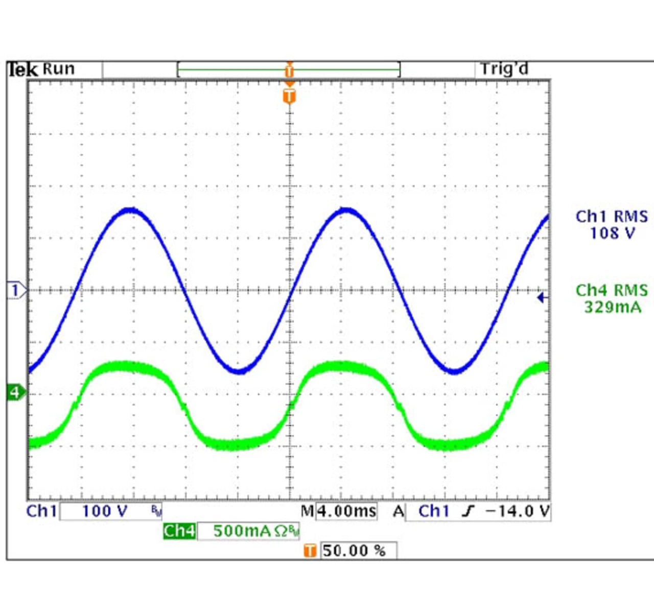
Eingangsspannung und der Eingangsstrom des einstufigen PFC-Schaltnetzteils
Bild 5: Die Eingangsspannung (Ch1, blau) und der Eingangsstrom (Ch2, grün) des einstufigen PFC-Schaltnetzteils entsprechend Bild 4 - gemessen am 110-V-Netz.
© Fairchild

Die Kapazität des Ausgangskondensators berechnet sich gemäß Gleichung (26):

«math xmlns=¨http://www.w3.org/1998/Math/MathML¨»«mo»(«/mo»«mn»26«/mn»«mo»)«/mo»«mo»§nbsp;«/mo»«msub»«mi»C«/mi»«mi»A«/mi»«/msub»«mo»=«/mo»«mfenced close=¨|¨ open=¨|¨»«mrow»«mfrac»«mrow»«mi»n«/mi»«mo»§#183;«/mo»«mi»K«/mi»«mo»§#183;«/mo»«mi»§#238;«/mi»«/mrow»«mrow»«mn»2«/mn»«msub»«mi»§#960;f«/mi»«mi»Netz«/mi»«/msub»«mo»§#183;«/mo»«mi»§#916;U«/mi»«/mrow»«/mfrac»«mo»§#183;«/mo»«mfrac»«mrow»«mn»0«/mn»«mo»,«/mo»«mn»143«/mn»«/mrow»«mrow»«mn»1«/mn»«mo»+«/mo»«mn»0«/mn»«mo»,«/mo»«mn»53«/mn»«mo»§#183;«/mo»«mi»K«/mi»«/mrow»«/mfrac»«mo»-«/mo»«mfrac»«msub»«mi»I«/mi»«mi»A«/mi»«/msub»«mrow»«mn»4«/mn»«msub»«mi»f«/mi»«mi»Netz«/mi»«/msub»«mo»§#183;«/mo»«mi»§#916;U«/mi»«/mrow»«/mfrac»«/mrow»«/mfenced»«/math»

«math xmlns=¨http://www.w3.org/1998/Math/MathML¨»«mo»=«/mo»«mn»3314«/mn»«mi»§#181;F«/mi»«/math»

Vier Elektrolytkondensatoren mit je 1000 µF sollten ausreichend sein. Den vollständigen Schaltplan zeigt Bild 4, die Messergebisse dieser Schaltung zeigt Bild 5.

Da bei einer Stromversorgung für LEDs der Ausgangsstrom konstant sein sollte, um die gleiche Helligkeit für jede der in Reihe geschalteten LEDs sicherzustellen, verfügt die Schaltung über eine Strom-Rückkopplungsschleife. Um sicherzustellen, dass der Leistungswandler auch mit unterschiedlich vielen LEDs gut funktioniert, wird ein Spannungsregler hinzugefügt, um eine ausreichend hohe Betriebsspannung für den Controller zu liefern.

Der Wirkungsgrad und der Leistungsfaktor des so dimensionierten PFC-Schaltnetzteiles wurden gemessen, die entsprechenden Werte sind in der Tabelle zusammengefasst:

UEingang LeistungsfaktorKlirrfaktor PAusgang PEingang
Wirkungsgrad
90 V 0,98 13,6% 29,30 W 34,9 W 84%
110 V 0,97 15,4% 29,33 W 34,1 W 86%
220 V 0,94 25,1% 29,30 W 34,0 W 86%
264 V 0,92 26,7% 29,30 W 34,4 W 85%

Die mit einem einstufigen PFC-Schaltnetzteil realisierte 30-W-Stromversorgung für LEDs erreicht über einen weiten Eingangsspannungsbereich die gewünschten Zielwerte: Leistungsfaktor >0,9, Wirkungsgrad >85 %.


Die Stromversorgungsschaltung erreicht für den gesamten Eingangsspannungsbereich einen Leistungsfaktor von mehr als 0,9 und einen Wirkungsgrad über 85 %.


  1. PFC- und DC/DC-Wandler in Einem
  2. Entwurf eines einstufigen PFC-Schaltnetzteils
  3. Schaltungsbeispiel
  4. Literatur & Autoren

Lesen Sie mehr zum Thema


Das könnte Sie auch interessieren

Jetzt kostenfreie Newsletter bestellen!