Bus Systems
Physical Layer Compliance Test Challenges for MOSTnG
Fortsetzung des Artikels von Teil 2
MOST test strategies
Buying test and measurement equipment is a long term investment. Therefore, the flexibility of the measurement equipment is a key issue. The equipment should be adaptable to a wide range of different signals.
Jobangebote+ passend zum Thema

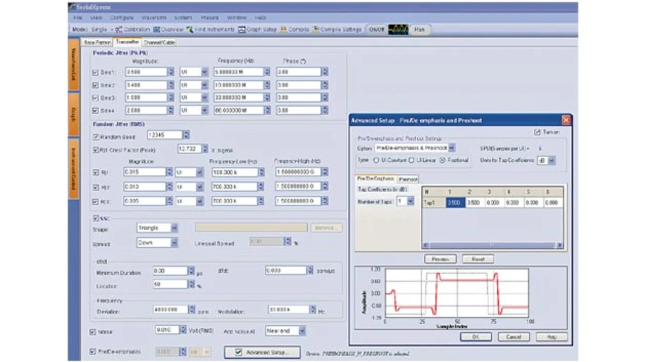
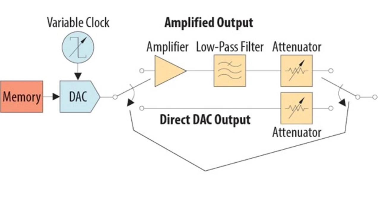
In particular, difficult receiver stress tests like jitter tolerance, robustness against noisy environments and other interference tests can easily and repeatedly be performed by using arbitrary waveform generators (AWGs). AWGs use the principle of Direct Digital Synthesis to enable the creation of physical layer test signals straight from a mathematical description (see Figures 4 and 5). Tests with realistic and precisely defined signal impairments can be applied under constant and repeatable conditions using AWGs. The arbitrary waveform generator should feature high signal fidelity and dynamic range as well as a sufficiently high sample rate to simulate different test scenarios and support the trend of ever faster busses.
A wide range of various jitter sources can be added to the test pattern at the same time with the mathematical direct synthesis method. 10 bit vertical resolution and small horizontal sample interval give the necessary accuracy to generate the appropriate test pattern. Generation of specific jitter test patterns could be calculated with different tools: Matlab scripts can be used to calculate the test patterns, and then export them into the AWG memory. Or you can use SerialXpress, optional software by Tektronix, which will take the key characteristics of the waveform and generate the required test pattern. It is even possible to embed or de-embed the transmission path characteristics into the test pattern by using S-parameter files. This is very helpful when characterising the quality of connectors as well as interconnect devices and their influence on the eye diagram and jitter analysis results.
In order to test the quality of the receiver and transmission path when handling the different stress patterns, there needs to be a way to compare the transmitted bits with the received data. For instance, the internal loop function of the receiver chip could be used to retransmit the received bits from the Rx to the Tx path. The retransmitted pattern can then be compared with the original signal using the built-in bit error detection function for NRZ-based signals in an instrument such as the Tektronix DSA70000 series oscilloscope. Another example is that the receiver chip might also have the ability to perform the bit error analysis internally on a predefined bit pattern.

- Physical Layer Compliance Test Challenges for MOSTnG
- MOST testing challenges
- MOST test strategies
- The authors: