Bus Systems
Physical Layer Compliance Test Challenges for MOSTnG
Fortsetzung des Artikels von Teil 1
MOST testing challenges

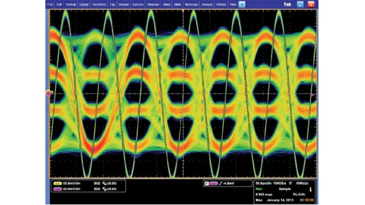
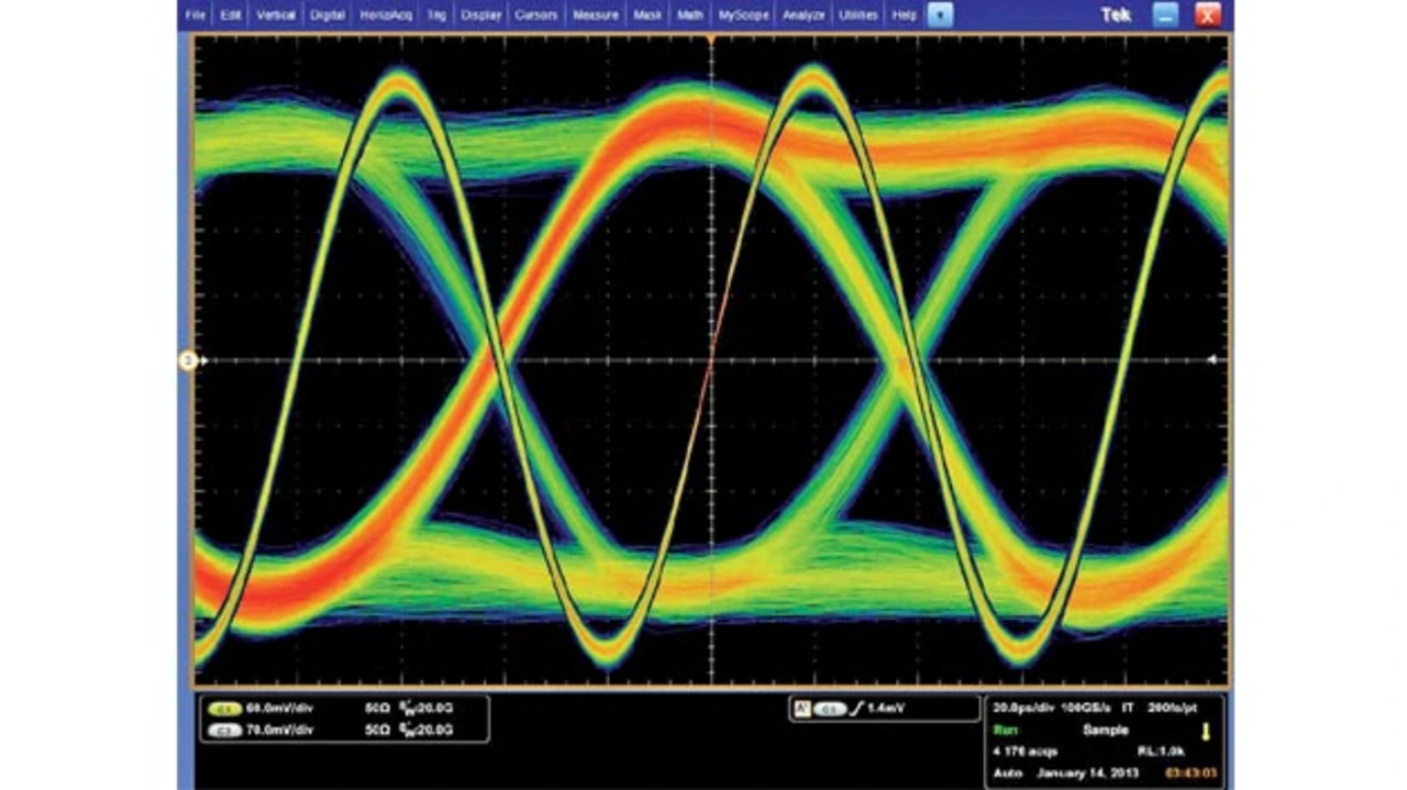
The choice of transmission signaling, such as PAM4 (see Figure 1) or NRZ (Figure 2), will affect all subsequent components and methods. Various problems need to be considered: How is the clock recovered from the signal for eye diagram analysis? Is the test point after equalisation accessible within the receiver section, or which equalisation technology should be used? Is it possible to use just a simple equaliser? This simple equaliser will increase any high frequency losses, but it will also increase noise at the same time. Or should it be a more complex equaliser, like a FFE/DFE (feed forward/decision feedback equaliser) for NRZ-based signals?
Jobangebote+ passend zum Thema

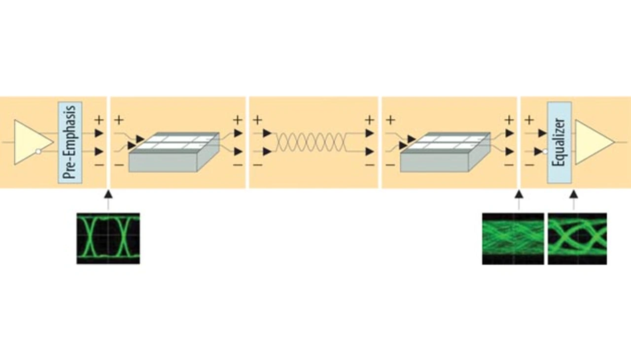
For the correct validation of the eye diagram, the same equalisation method has to be used by the test equipment. If the test point after the built-in equaliser section of the receiver is accessible, then the test situation is not very complex. However, if the equaliser is implemented within the receiver chip then the equaliser has to be implemented in the test equipment as well. This could be done with mathematical post-processing after test signal acquisition.
Reliability of the transmission system is a key feature in this technology (Figure 3). How much jitter can be added by the transmission medium before the receiver starts to see bit errors? This kind of test could be done with a stress pattern generator. The challenge here is to have a generator with fine amplitude and timing resolution. This allows to add exact amounts of jitter and/or noise in order to find the critical tolerance point.
With high data rates, the impact of test signal probing has an impact which cannot be ignored. Compensating for probing and adaptor losses is necessary with de-embedding.

- Physical Layer Compliance Test Challenges for MOSTnG
- MOST testing challenges
- MOST test strategies
- The authors: