Wireless Sensing
S-Band FMCW Radar with MIMO Antenna Array Beamforming
A radar can be used to locate a buried object. Therefor the radar should operate at low frequencies to be able to penetrate the medium the object is buried in and it should have a high spatial resolution to be able to discriminate between the object and reflections caused by the medium.
Wireless sensing offers a possibility in the detection of buried objects, as electromagnetic waves in the microwave region are able to penetrate many materials. A radar can be used to measure the range and DoA (Direction of Angle) of the buried object, such that it is possible to exactly locate the object. The radar used in these applications should meet two criterions, first, it should operate at low frequencies to be able to penetrate the medium the object is buried in and second, it should have a high spatial resolution to be able to discriminate between the object of interest and clutter reflections caused by the medium. The presented radar is based on an FMCW architecture and operates in the S-band, 2 to 4 GHz, to meet the first criterion. Spatial resolution in the cross-range dimension is accomplished by using a MIMO antenna array made of overall six broadband Vivaldi antennas, two transmit and four receive antennas. A calibration process to calibrate the phase and amplitude of the MIMO array is presented, requiring only one measurement of a reference target at a known position.
Introduction
This article is a revised version of the article published by the authors at the 'Kleinheubacher Tagung 2021'.
The proposed radar is based on the FMCW (Frequency Modulated Continuous Wave) radar principle and it is capable to produce 2-dimensional images with a MIMO (Multiple Input Multiple Output) antenna array. The radar does frequency chirps over the S-Band (2 to 4 GHz) with a ramp rise time of 500 µs, together with the large pulse bandwidth of 2 GHz, a range resolution of 7.5 cm is accomplished. The operating frequency allows the detection of foreign objects made of metal in biological dielectrics, due to fairly good penetration properties at these frequencies [1].
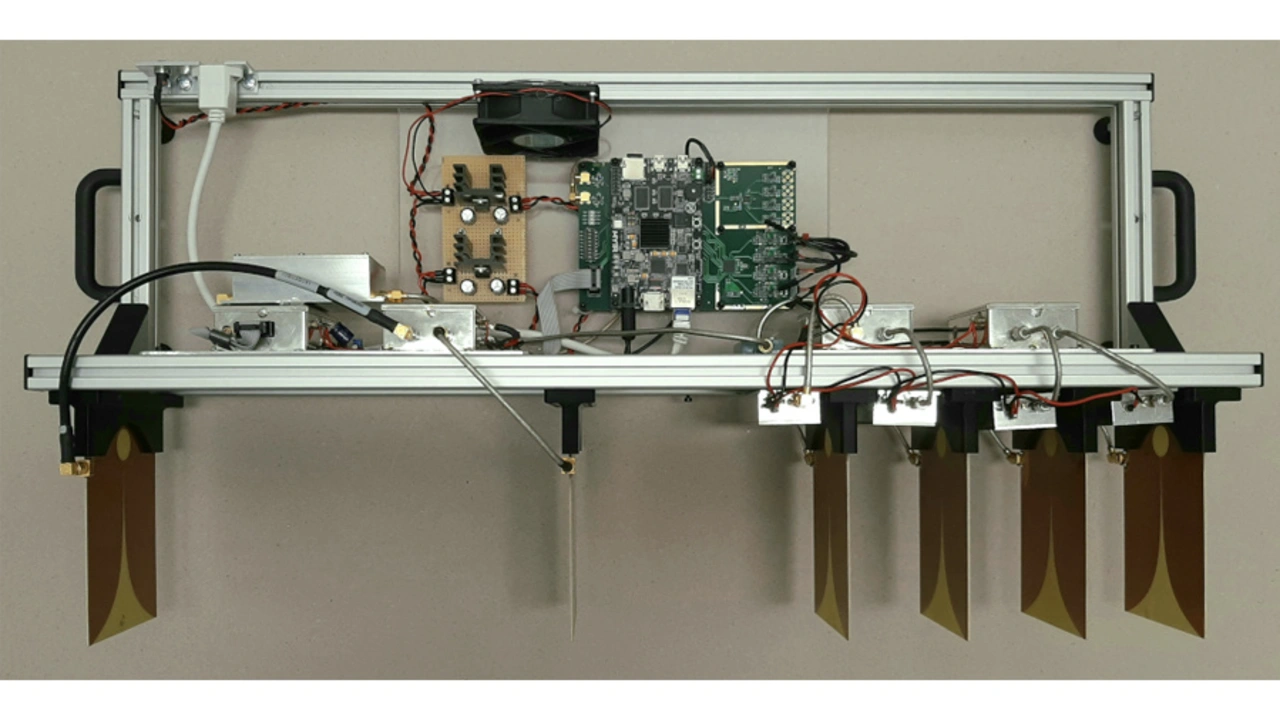
The proposed radar system can be seen in figure 1. The picture shows from bottom to top: the MIMO antenna array, consisting of six Vivaldi antennas, shielded rf front ends and DC power supply distribution as well as an FPGA data acquisition board. A more detailed description of the radar architecture is given in the following sections.
MIMO FMCW Radar Architecture
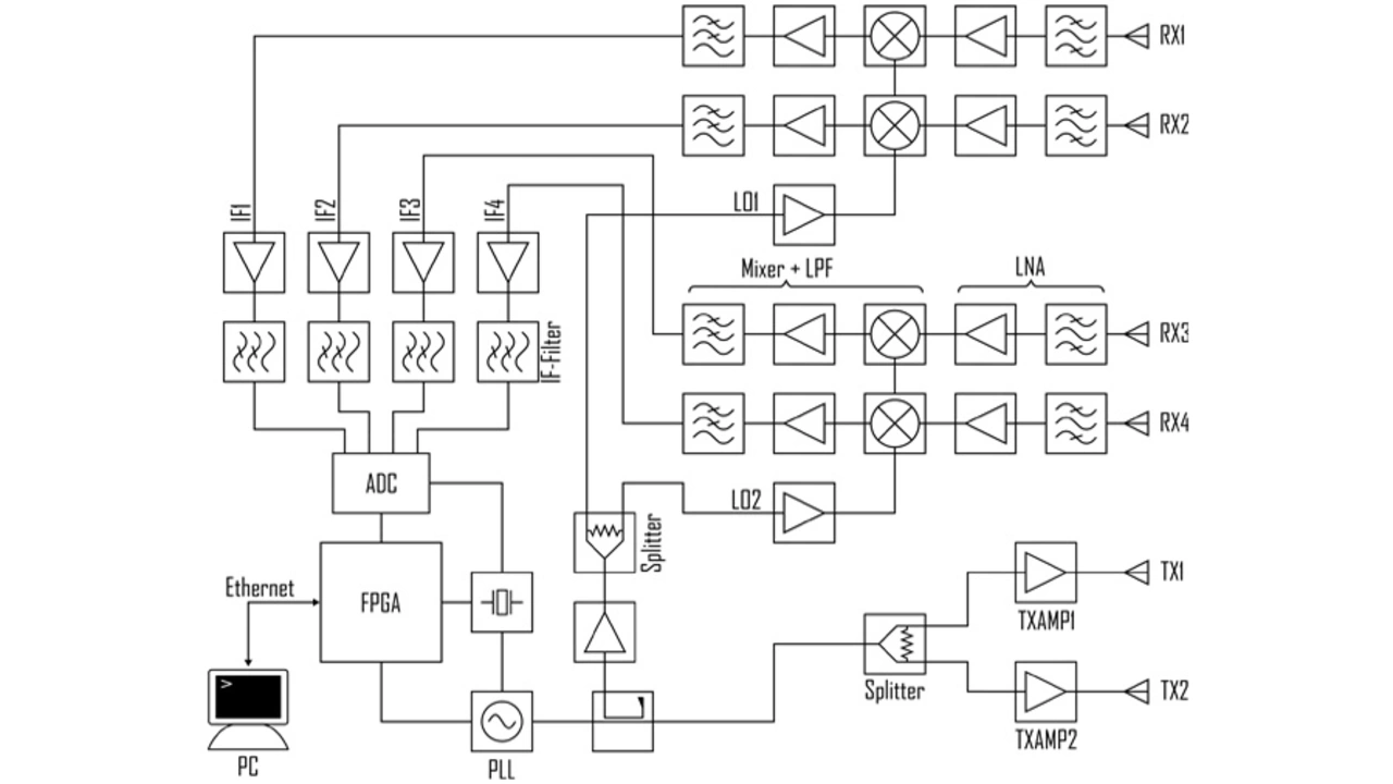
The block diagram of the proposed radar can be seen in figure 2. The oscillator, that generates the frequency ramp, consists of a fully integrated PLL (Phased Locked Loop) and an octave tunable VCO (Voltage Controlled Oscillator). The PLL has a build in frequency ramp functionality, that allows fast frequency ramp modulations and ensures good ramp linearity, that is crucial for FMCW radars [2]. The oscillator signal is then split into two signals, one for the receive part and the other for the transmit part. A directional-coupler is used to split the signals to ensure good isolation between the receive and transmit part, to minimize internal cross-talk. Furthermore, the signal is split for the local oscillator inputs of the receive mixers and transmit amplifiers.
The transmit part consists of two amplifiers which can be turned on or off independently. The amplifiers are switched, so that only one transmit antenna is active at a time. This is done because the MIMO channels are distinguished by the TDM (Time Domain Multiplexing) method. To improve the isolation of the amplifiers in the off state, a microwave switch is set in front of each amplifiers, resulting in an isolation better than 50 dB.
The receiver part is made of four heterodyne downconverter channels, allowing the simultaneous capturing of all four receive antennas. The signals of the receive antennas are first filtered with a short circuited stub bandpass filter [3] and then amplified by a low noise amplifier. The RF signals are then down-converted by two fully integrated mixers (ADL5802). These ICs contain amplifiers for signal conditioning and two independent mixer channels. The IF signals are then low-pass filtered and sampled by a four channel 14 bit 50 MSPS ADC (ADC3442). The data is then filtered and down-sampled to 5 MSPS by an FPGA to improve the dynamic range of the ADC.
The captured and conditioned data is then send to a computer via a gigabit ethernet connection and then processed to a radar image in Matlab. The fast interface enables live radar images with currently frame rates of around 10 Hz.
Single Array Element – Vivaldi Antenna
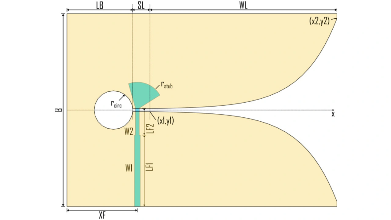
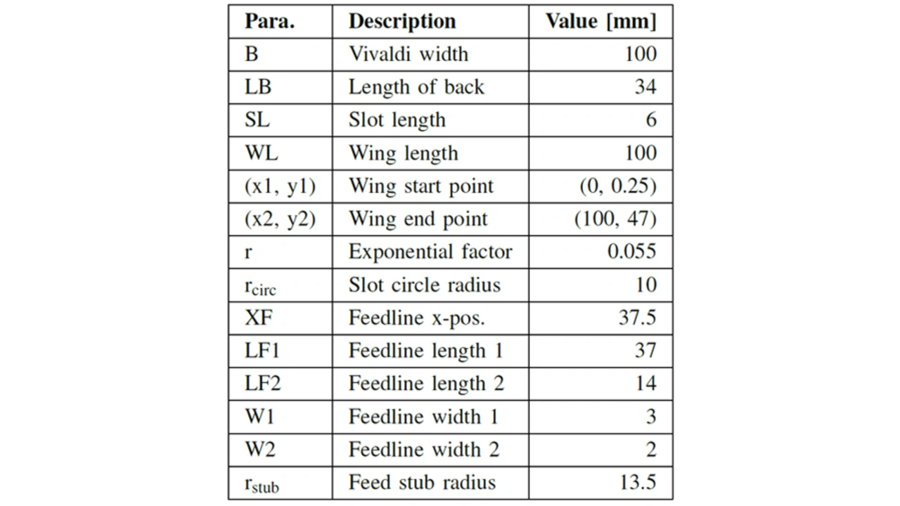
The single antenna element of the array is a coplanar Vivaldi with a microstrip feedline on the bottom side. In figure 3 is a structural drawing with dimension parameters of the proposed Vivaldi antenna, where the yellow area indicates the top copper layer and the green area is the bottom layer. The dielectric layer between the copper layers is commonly used 1.6 mm thick FR-4 substrate with a dielectric permittivity of about 4.6.
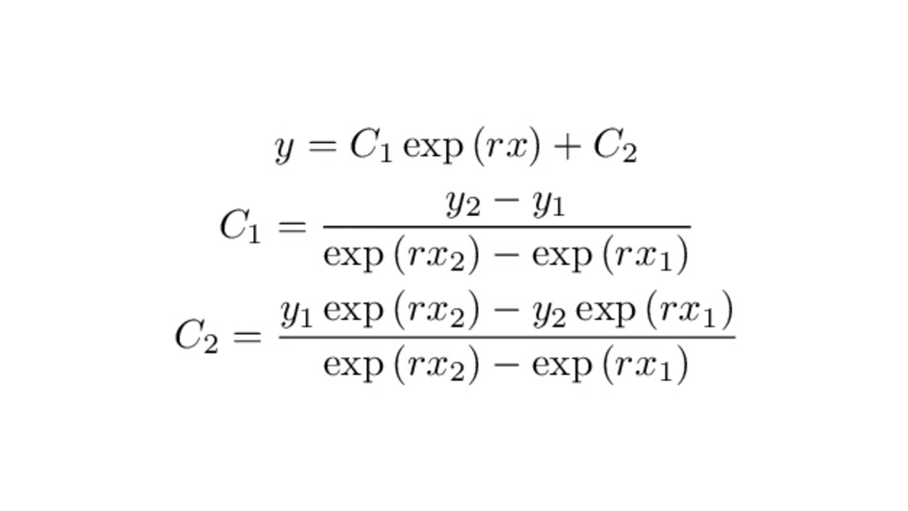
The exponential opening of the slot line is defined by two fixed points, the starting and end point, (x1, y1) and (x2, y2), and a parameter r, which defines the exponential growing rate. The opening curve is defined by equation 1 [4], [5].
To improve the return loss, a quarter waveform transformer (W2, LF2) is implemented in the feed structure and together with the radial stub, the fairly high slotline impedance of the Vivaldi structure is matched to a 50 Ohm microstrip line, at which end a SMA-connector is installed.
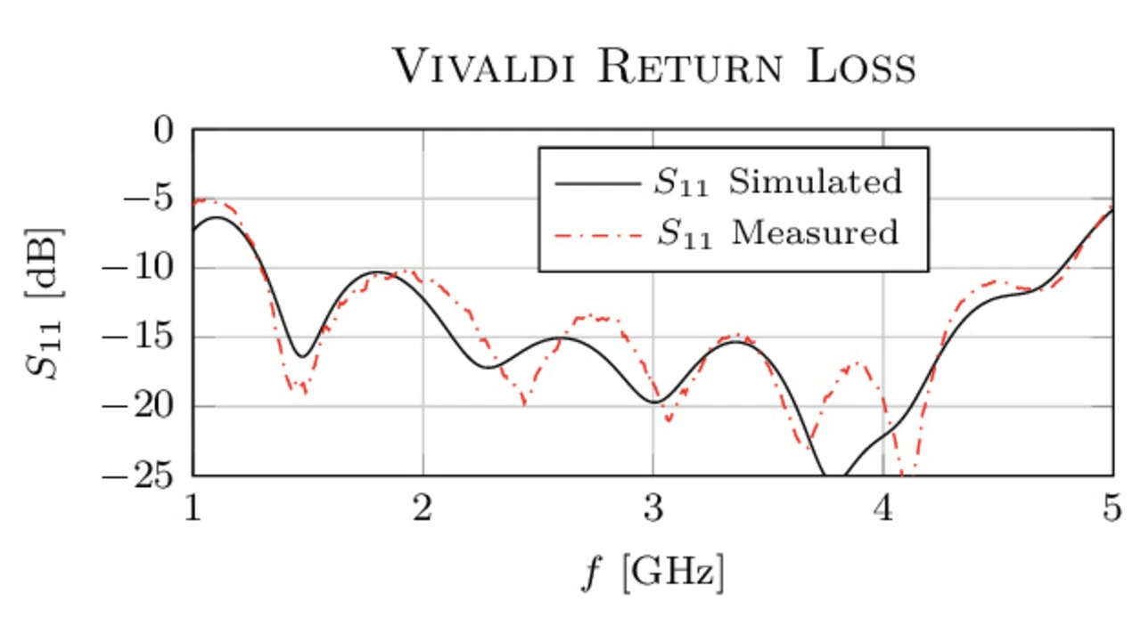
The Vivaldi structure was simulated in order to refine the parameters empirically, so that the return loss is below -10 dB in the operating frequency range of 2 to 4 GHz and the overall antenna area is kept small to make it suitable in an array. The simulated and measured return loss of the finished antenna can be seen in figure 4.
ULA Antenna Array
The antenna array is made to beamform the received signal in the azimuth direction. This is accomplished with a uniform linear array (ULA), in which the transmit (TX) and receive (RX) antennas are positioned linear and each antenna in the TX and RX group is spaced uniformly [6].
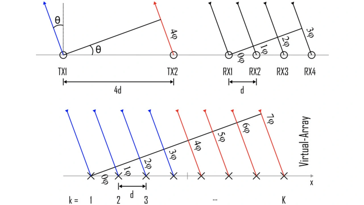
In figure 5, the structure of the realized ULA can be seen and the formation of the virtual antenna array is depicted. The array uses two TX and four RX antennas, this results in a virtual array with K = 8 elements. The distance between the RX antennas is d = 7 cm and the TX antennas are spaced by 4d. The distance between TX2 and RX1 should be large enough so that the cross-talk or mutual coupling between TX and RX is small.
Consider a point target in figure 5 is located at an angle \theta far away enough from the array to meet the far-field criterion, so that the transmitted and received waves of the array can be modeled parallel. It can be seen that the signals transmitted by antennas TX1 and TX2 already have a phase offset of 4ϕ due to the spacing of 4d. Because each RX antenna is spaced by d, there is a phase offset of φ between each RX signal. Now, the phase offsets of the TX and RX antennas can be added for every TX-RX combination and the resulting phase offsets of the virtual array ranges from 0ϕ to 7ϕ. Because every TX-RX signal combination is distinguishable with the MIMO process, a so-called virtual array can be spanned with two more virtual antennas than physical antennas. Theoretically, a MIMO ULA array with QTx transmit and QRx receive antennas can span a virtual array with Q = QTx QRx virtual antennas.
In the proposed radar, each TX-RX signal combination is distinguished by time domain multiplexing (TDM). Other proceedings like frequency division (FDM) or code division (CDMA, OFDM, etc.) multiplexing are possible and discussed in [7]. The time domain multiplexing enables the best channel orthogonality with the downside of a longer measurement interval.
- S-Band FMCW Radar with MIMO Antenna Array Beamforming
- FMCW MIMO Array Calibration


