NFC-WLC Wireless Charging Standard
Optimize Designs in the Face of Size, Cost and Performance
NFC wireless charging answers a growing need in the market for technology to charge small devices such as smart watches, styluses and smart glasses. Circuits for NFC wireless charging need dedicated wireless charging components, and have their own special design considerations.
The NFC-WLC standard for wireless charging issued by the industry’s NFC Forum provides a set of specifications to enable a listener (receiver) to harvest power for charging a battery from the output of a poller (transmitter). As with other NFC standards, the NFC-WLC standard also provides for communication between the poller and listener – this communications channel is used to match power transfer operations to the needs of the listener’s battery, and to report to the poller data such as the battery state of charge.
NFC wireless charging answers a growing need in the market for technology to charge small devices such as smart watches, styluses and smart glasses, or other types of portable device which have a battery of up to 400 mAh capacity. The advantages of using NFC wireless charging over wired technologies such as USB Power Delivery are:
- Increased reliability – every wired connection is a potential point of failure. Miniature connectors are particularly prone to damage from mechanical stresses such as bending.
- Increased design freedom – consumer and wearable devices have a limited surface area. The designer can optimise the shape of the device and the use of its surface when they do not have to accommodate a connector.
- Easier to achieve a high Ingress Protection (IP) rating – by eliminating mechanical connections, manufacturers can close a point of entry for contaminants such as water, sweat and dust.
There is another open standard technology for wireless charging: Qi. But for various reasons, the Qi technology is poorly suited to the charging of small or wearable devices. While it is successfully used to charge mobile phones and other devices with a battery of at least 3,000 mAh capacity, it requires a large antenna in the receiver. For battery charging loads of around 1 W, a Qi system is generally too bulky and too expensive. Unlike NFC-WLC, it also provides a limited data communication capability.
The design challenges in implementing NFC wireless charging in portable or wearable devices
The purpose of an NFC-WLC circuit is different from that of an NFC communications circuit, such as the NFC circuit in a smartphone used for contactless payments or Bluetooth network pairing. Put simply, the job of an NFC wireless charging system is to prioritize power transfer over communications operations. So it is assumed that the poller’s and listener’s antennas will be placed close together to achieve the highest possible coupling factor. This has the effect of detuning the poller and listener relative to each other, reducing the effective data-transfer rate.
In NFC communications, by contrast, the requirement is to maximize the effectiveness of signal transfer over a large operating volume (with the antennas at a distance from each other).
This means that NFC wireless charging circuits need dedicated wireless charging components, and have their own special design considerations, different from those of an NFC communications system. A typical overview of an NFC-WLC system based on the PTX100W transmitter IC from Panthronics is shown in Figure 1.
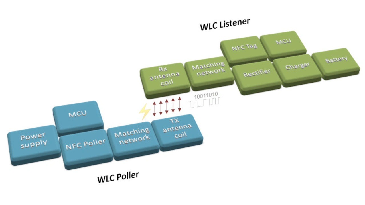
The poller takes DC power from a low-voltage source, and converts it into an RF field at the standard NFC frequency of 13.56 MHz. On the receiver side, the listener extracts the power from the RF field, and converts it to a DC charging current supplied to a battery. The poller and listener negotiate power transfer operations via the NFC interface, using standard NFC signalling protocols.
In implementing such a system, designers have to operate within constraints particular to the wireless charging application. This calls for the adoption of technical solutions which balance the need for fast charging performance and reliable signalling against the constraints of size and cost.
The most important challenges which this presents are:
Antenna design and matching – in products such as earbuds or styluses, there is very little space for the antenna. Its operation might be compromised by the proximity of metal surfaces.
Depending on the application, the product manufacturer might wish to optimize for efficiency, for high power transfer, for antenna misplacement, or for some other factor. Effective development therefore calls for the flexibility to optimize key antenna parameters – principally Quality (Q) factor, resonance frequency, and coupling factor – for the needs of the application.
The matching network of the poller is used to transform the complex impedance of the antenna in order to maximize the power delivered to the listener. In a conventional NFC communications application, the antenna in the poller is required to read a listener’s signals over the longest possible range. The target impedance of the poller antenna is configured for an unloaded condition, and the process to achieve the target impedance is focussed on matching a single resonance.
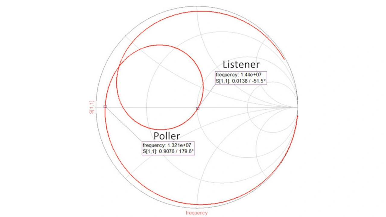
In the case of NFC WLC, the poller’s and listener’s antennas are tightly coupled: the coils strongly influence each other (a mutual inductance), and with an increased level of complexity. In addition, the rectifier and the battery act as a complex non-linear load, causing a change to the overall quality factor of the system. So the target frequency for the antenna is typically different for the poller and the listener in order to prevent the two systems from detuning each other. This means that the Q value is much lower than in a standard NFC communications application.
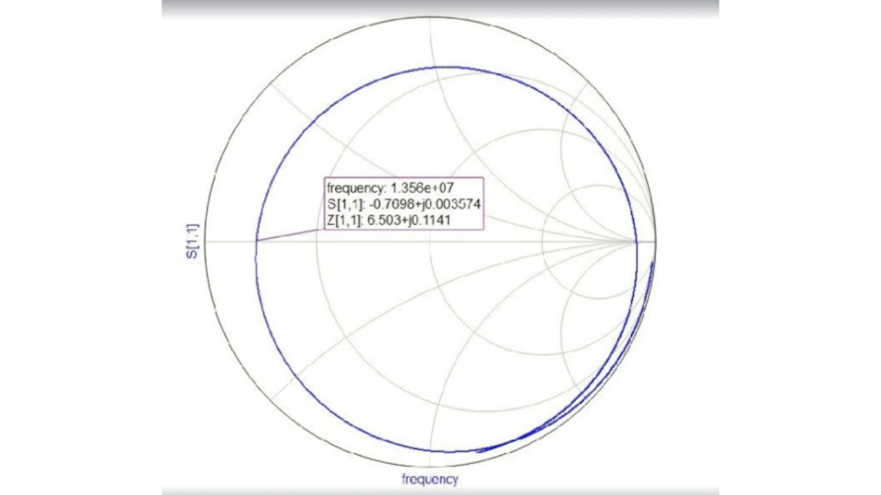
Spatial freedom is another distinguishing characteristic of NFC WLC compared to other technologies. This factor is typically required in order to identify the boundary condition for the charging volume – the distance which the two antennas can be apart while still maintaining adequate charging performance.
This volume is limited by antenna size. In addition, the designer needs to maintain a high enough Q value to reduce thermal losses and maintain a safe system operating temperature.
Efficiency and battery charge time – consumers care about battery charge time, and charge time will be one of the key figures of merit in any wireless charging design project. Important factors which affect battery charge time include:
- The power efficiency of the transmitter
- Antenna-to-antenna efficiency
- The efficiency of the rectifier circuit
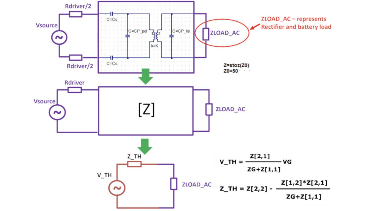
To characterise and optimise the system, a synthesis of all the blocks can be simulated applying the Thevenin equivalent approach. This method enables the designer to reduce the complexity of the system and to dynamically optimize the system based on the requirements of the application.
Figure 3 shows a schematic of these blocks. V_TH, Z_TH are complex parameters, and they are unique for every combination of component values and other parameters (such as coupling). They are not dependent on ZLOAD_AC.
The ZLOAD_AC depends on:
- The rectifier topology and components (diodes)
- Output DC power (Pout_DC) – the power delivered to the DC load
- Thevenin Impedance Z_TH
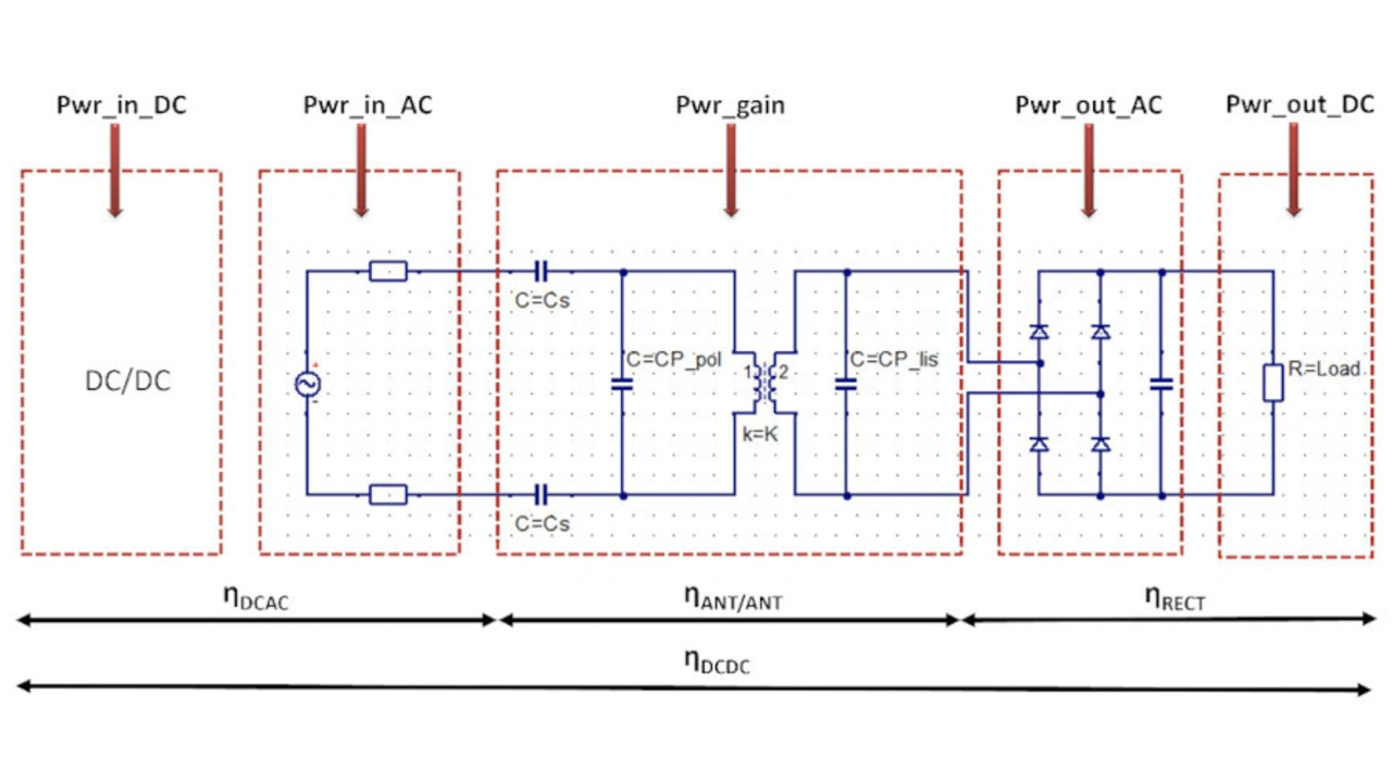
System efficiency can be modelled based on the efficiency of the various blocks.
Efficiency is given by the following equation:
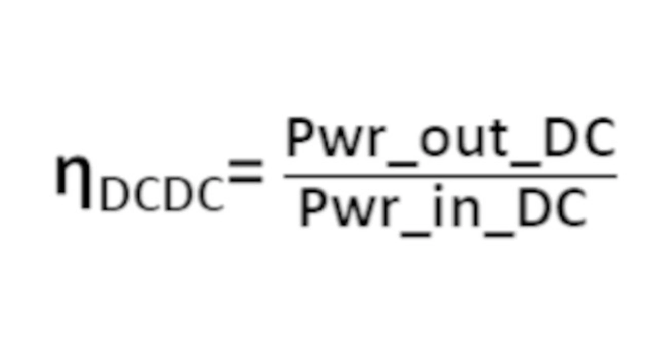
The DC-to-AC efficiency represents the ability of the NFC transmitter to convert the input DC supply voltage to an AC signal to the antenna.
The antenna-to-antenna efficiency is calculated from the antenna coupling factor, Q factor and matching, and represents physically the system poller/listener in charging mode.
The ηRECT represents rectifier efficiency, and depends on the choice of topology.
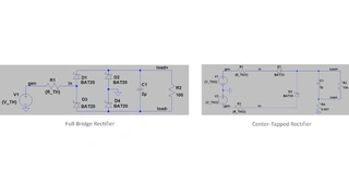
For most wireless charging applications, the full-bridge topology (Figure 6) is used for rectification due to its simple structure. In a traditional analysis, the rectifier input impedance is modelled as a pure resistive load (Figure 7).
Figures 6 to 10
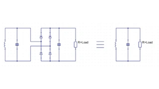
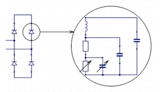
This assumption is invalid at an operating frequency of 13.56 MHz. At this frequency, the parasitic parameters of the rectifier become obvious, and mean the diodes are no longer an ideal switch. A high-order circuit model is used to describe the diode characteristics (Figure 8).
The behaviour of the diodes in a rectifier changes with the frequency and the load applied: the input resistance and capacitance are negligible at low frequency, but need to be taken into account in NFC WLC.
The additional capacitance of the rectifier directly affects the resonance frequency of the system (Figure 9). It is therefore necessary to compensate for it with the parallel matching capacitors at the listener’s coil.
The rectifier can be analysed by simulation, when data from the manufacturer are available, or empirically with a dedicated measurement set-up (Figure 10).
This technique allows the designer to characterise the rectifier, and to predict its behaviour in any load condition to maximize the efficiency of this block.
System size and cost – by keeping component count and board footprint to a minimum in both the listener and poller circuits, wireless charger manufacturers can reduce system size and cost, and gain greater design flexibility to add desirable features or to reduce total product size.
- Optimize Designs in the Face of Size, Cost and Performance
- Profound impact of RF architecture on wireless charging operation

