Cordless Kitchen
Wireless energy transfer in a kitchen
Fortsetzung des Artikels von Teil 1
Proposed topology with low disturbance
Figure 4 shows the proposed topology – the current source (CS) parallel resonant topology – which might be easier to meet the non-functional requirements. An attempt is made to meet the functional and non-functional requirements by modifying the transmitter side.
Lchoke is placed at the DC side of the inverter stage to realize a current source driven parallel resonant inductive coupler. To analyse the properties of this topology, mathematical analysis together with the simulations in the time and frequency domain can be performed. It can be observed that, due to the presence of Lchoke it is harder to perform the frequency domain simulations for this topology. One can reduce the circuit with the proper mathematical analysis and proceed with the further evaluation. In this case, to proceed with the analysis following (realistic) values are chosen:
fTx = fRx = 33 kHz
L1 = 290 µH
L2 = 290 µH
C1 = 1/(4 π² fTx²Lr)
C2 = 1/(4 π²fRx²L2)
Lchoke = 1 mH
Lr = L1||2 Lchoke
k = 0.35
RL = 10 Ω
Vin = 325 V DC (for time domain)
Analysis of CS parallel resonant topology
The topology is based on the principle of parallel resonance in which the circuit offers maximum impedance at the resonant frequencies. For this topology and calculated circuit component values, the resonant frequency of the whole system (fr1) is observed to be 28.2 kHz. With the help of these calculated circuit component values, the time domain simulations of the circuit shown in figure 4 can be performed.
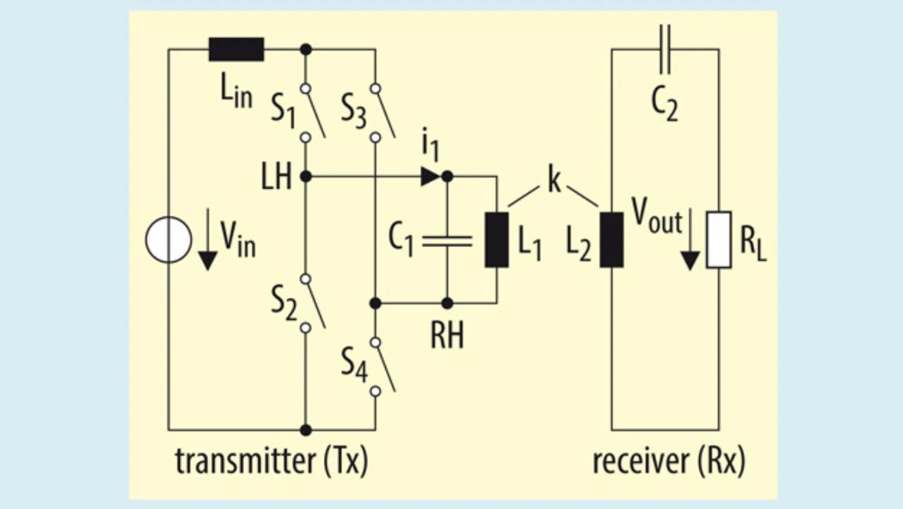
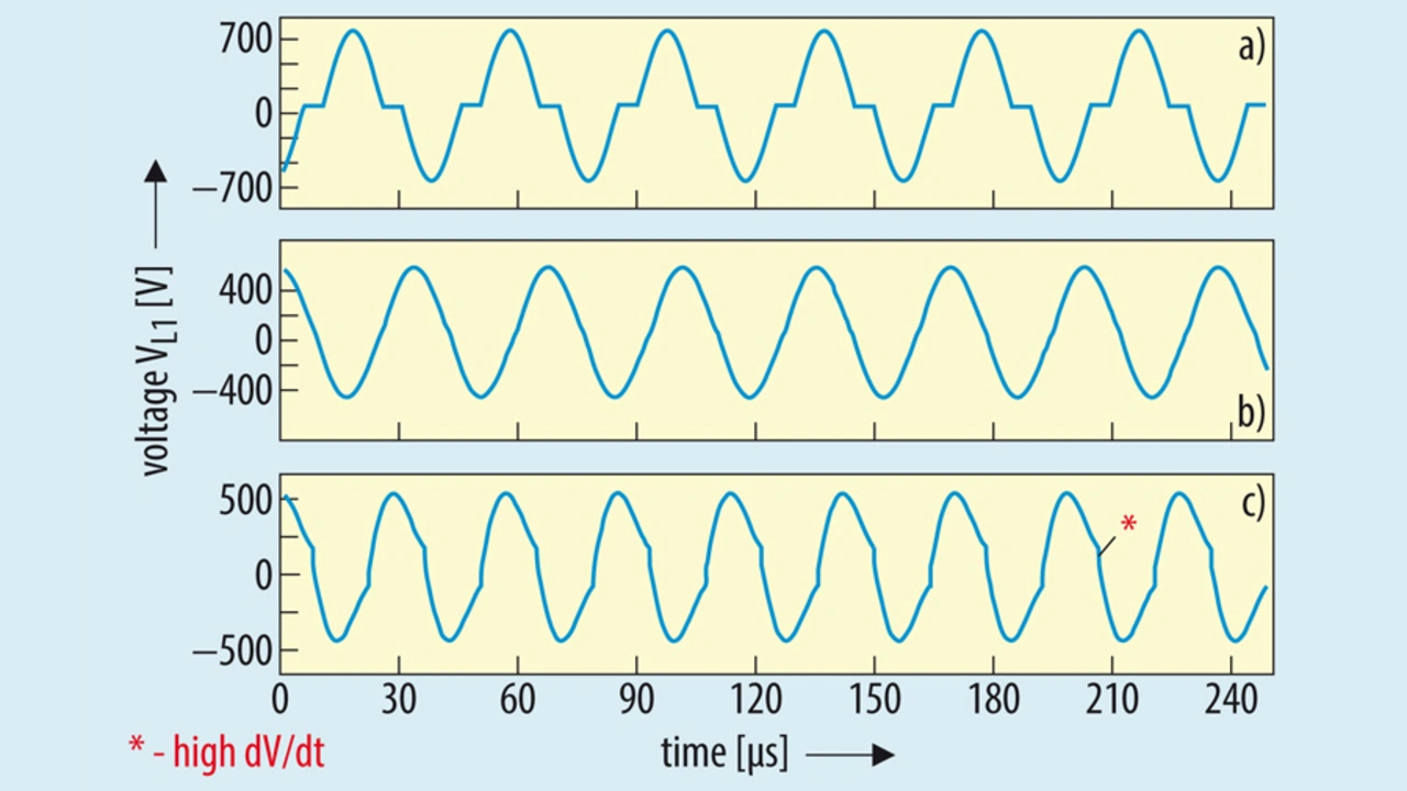
Figure 5 shows the voltage across the transmitter coil of the resonant inductive coupler when the inverter stage is operated at fop < fr1, fop = fr1 and fop > fr1. Interestingly from figure 5, it can be seen that when the inverter stage of the transmitter is operated at or below the fr1, high dV/dt’s are not observed.
On the other hand, when the inverter stage is operated above the fr1, high dV/dt’s are observed. Therefore, based upon the requirements stated in the earlier section, the operation of this topology at or below fr1 is preferred. When the system is operated below fr1, the transmitter coil voltage waveform is almost a sine wave. It has an event near the zero crossing of the sine wave where the voltage is almost zero (Tfreeze).
Thus, for the analysis of the system operating at or below fr1, First Harmonic Approximation (FHA) can be used [3]. With the help of FHA, a simplified equivalent circuit of the system can be derived as shown in the figure 6. In the equivalent circuit shown in figure 6, R1 represents the equivalent series resistance of the transmitter coil L1, the choke coil Lchoke along with the the capacitor C1.
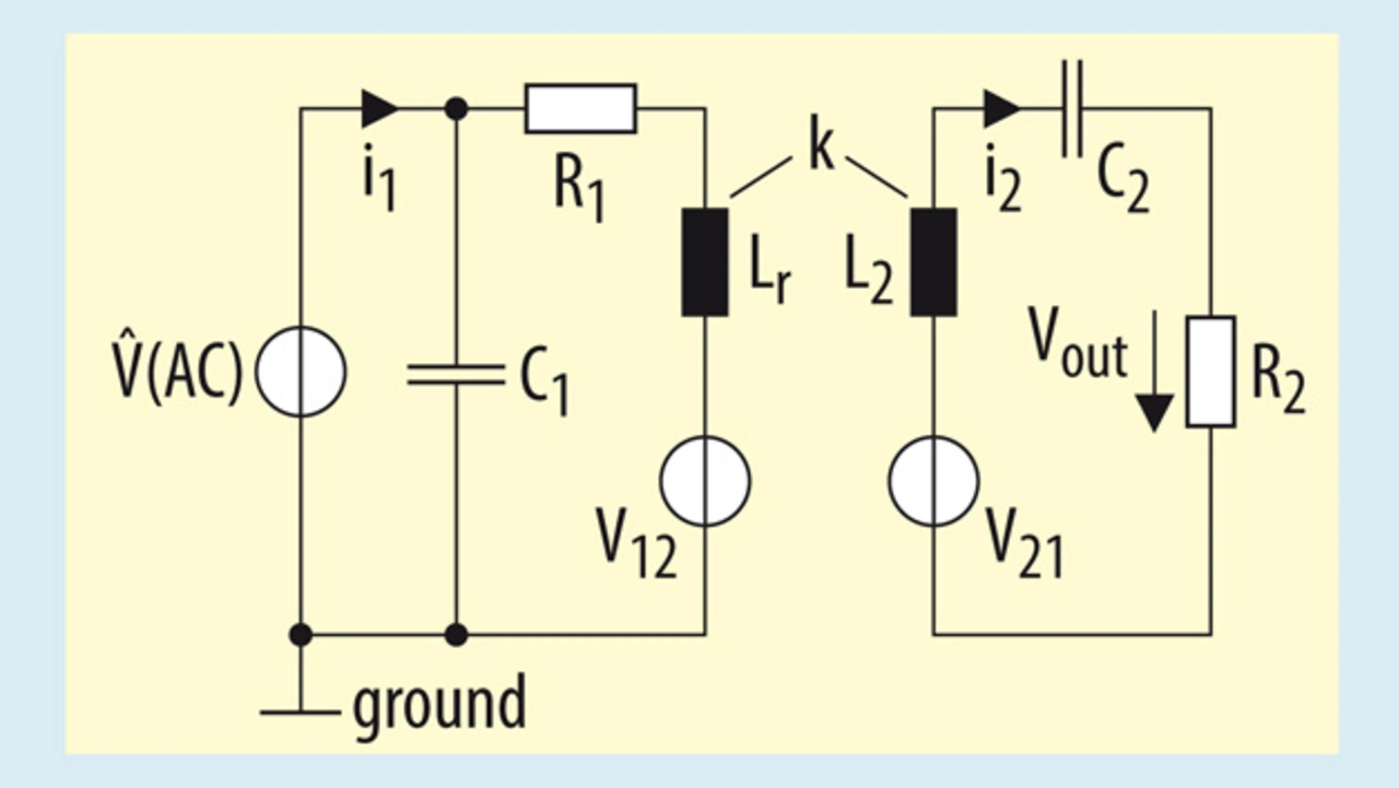
R2 represents the load resistance along with the equivalent series resistance of the receiver coil L2 and the capacitor C2. V12 represents voltage induced in the transmitter coil due to the mutual inductance (M) and the current flowing through the receiver coil (I2). V21 represents the voltage induced in the receiver coil due to the mutual inductance and the current flowing through the transmitter coil.
The FHA allows to replace the current source (IAC) and the capacitor C1 with an AC voltage source (^VAC). The transmitter capacitor C1 does not influence the receiver coil voltage gain but it does affect the phase of the input current (I1). Thus, the capacitor C1 can be regarded as a phase compensator for the input current drawn from the AC voltage source (^VAC).
Normalised First Harmonic Approximation
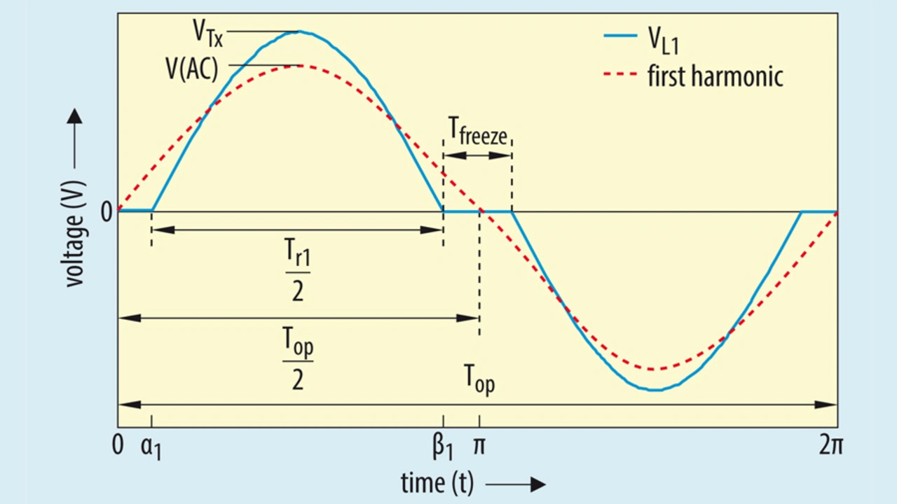
As shown in figure 5a, when the inverter stage of the transmitter is operated below fr1, the voltage across the transmitter coil appears to be a discontinuous function. With the help of time domain simulations, it can be observed that the peak voltage across the transmitter coil (VTx) and Tfreeze increases with decrease in operating frequency. Therefore, it can be stated that the amplitude of the first harmonic also changes with the change in operating frequency fop.
And thus, it is comparatively difficult to perform the frequency domain simulations for the equivalent circuit shown in figure 6. For better results from the frequency domain simulations, one has to model the source (^VAC) such that the amplitude of the first harmonic changes according to the operating frequency.
The relation between the amplitude of the first harmonic (VAC_FHA) and the operating frequency (fop) can be derived with the help Fourier analysis of the transmitter coil voltage waveform shown in figure 7. From figure 8 the relation between the peak amplitude (VTx) and operating frequency (fop) can be derived and is as shown in the equation below:
VTx = f(fop, fr) (1)
And, at fop = fr, the peak amplitude can be given by:
VTx_r =(Vin × π)/2 (2)
And with the help of Equation 1, the amplitude of the first harmonic (VAC) can be given by:
VAC_FHA = f(VTx, fop, fr) (3)
^VAC= (VAC_FHA/VTx_r) (4)
The normalized value (^VAC) can be used in figure 6 for the frequency domain simulations. It should be noted that the FHA is valid only at or below fr1. Therefore, the whole mathematical model for the frequency domain analysis is valid only at or below fr1.
Experimental measurements
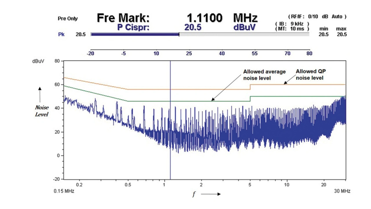
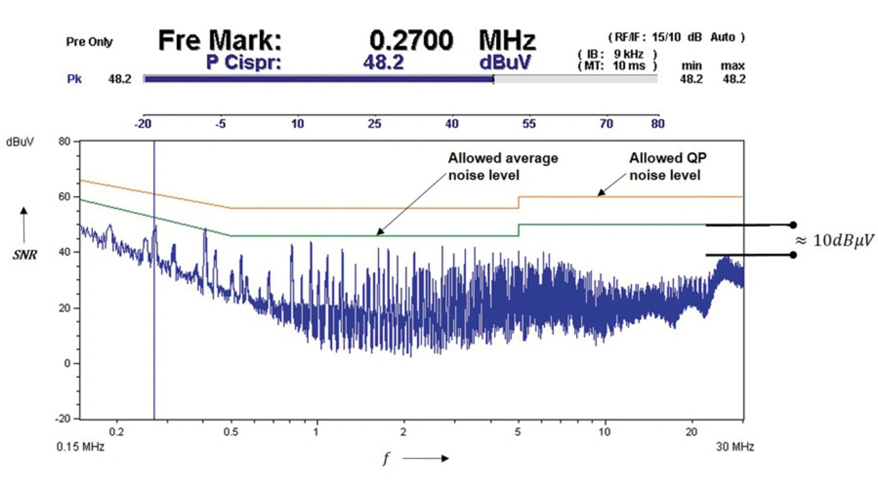
To verify the calculated and simulated results, a new prototype with the proposed topology was built. The EMC tests according to the standard CISPR14 were performed on the present system (series resonant topology) as well as the new prototype (CS parallel resonant topology, figure 2). Figure 8a and figure 8b shows the EMC measurements recorded for the present system and new prototype, respectively.
Both the figures shows the maximum allowed noise level for the Quasi Peak (QP) noise measurement according CISPR14 (uppermost line) and maximum allowed noise level for the average noise measurement according CISPR14 (middle line).
As per expectations, from figure 8b considerable reduction (10 dBµV) in the high frequency noise level can be observed in case of the CS parallel resonant topology. Therefore, the size of the mains filter can reduced.
Series resonance versus parallel resonance
The analysis and experimental results shows that, though the series resonant topology is easy to implement and widely used, it possesses some drawbacks when applied in the cordless kitchen system. It has advantages like the use of the low voltage switches, easy power control but, the EMI performance is relatively poor.
It can be observed that CS parallel topology is more suitable topology for the cordless kitchen system, when it comes to satisfy the non-functional requirements. High dV/dt’s do not occur, which offers good electromagnetic compatibility. The only disadvantages of the proposed topology are the high voltage rating of the power switches (more than 2 Vin) and the loss of control over the delivered power, as duty cycle control cannot be used. One can make use of the varying input voltage (Vin) to control the delivered power.
Literature
[1] Wassenaar, S.: Tunable wireless power transmitter. Philips Consumer Lifestyle B.V., unpublished.
[2] Itraj, M.: Mathematical modelling of cordless kitchen appliances. Philips Consumer Lifestyle B.V., unpublished.
[3] Steigerwald, R.: A comparison of half-bridge resonant converter topologies. IEEE Transactions on Power Electronics, 1988, issue 2, p. 174–182.
The authors

Will Ettes, B. Sc.
was born in the Netherlands and received his B.Sc. in Electrical Engineering in 1987 from the University of Applied Sciences in Leeuwarden. Since then he is a researcher at Philips Drachten in the north of the Netherlands, working on various topics in the field of Power Electronics, Control Dynamics & Communication systems, in the application areas: Domestic Appliances and Personal Care.
Since 1993 he is a Power Electronics lecturer at the University of Applied Sciences in Leeuwarden. Presently, he works as a Standardization Architect for Philips in the Netherlands, in the area of Wireless Power Transfer (WPT).
w.ettes@philips.com

Mahesh Itraj, M. Sc.
was born in India and received his B.Sc. in Electrical Engineering in 2013 from Pune University. He joined Tata Technologies in 2014 as a Design Engineer, specializing in passenger and commercial vehicle circuit schematics and wiring harness.
He received his M.Sc. in Electrical Engineering, specializing in Power Electronics, from TU Delft in the Netherlands. He delivered his master thesis on the topic „Topology study for an inductive power transmitter for cordless kitchen appliances“ and later on contributed in the standardzation process of the cordless kitchen, as an Hardware Designer. Presently, he works as a R&D specialist for Eekels Technology B.V. in the Netherlands, in the area of shore power converters.
m.itraj@eekels.com
- Wireless energy transfer in a kitchen
- Proposed topology with low disturbance


