ECPE Workshop
Power Modules of the Future
Fortsetzung des Artikels von Teil 2
Encapsulation and Thermal Management
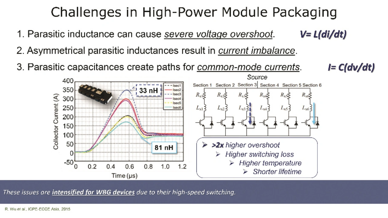
Day two was opened by Prof. C. Mark Johnson of the University of Nottingham. He presented a planar SiC module for 10 kV, which was developed in cooperation with the Center for Power Electronics Systems (CPES) at Virginia Tech in the USA and the Tianjin University in China. According to him, typical challenges for such applications are not only the parasitic inductances themselves, as they lead to high surge voltages. Since several SiC switches have to be connected in parallel within a module, there is also an inherent danger that these parasitic inductances will be asymmetrical, resulting in an asymmetrical current sharing among the parallel-connected MOSFETs (Fig. 5; [5]).

Other major challenges are the high field strength at the edges of the metallization, which can lead to partial discharges, and the high energies involved in a 10 kV module in case of a fault. At energies below 750 J, it must be ensured that the module always short-circuits in the fault event.
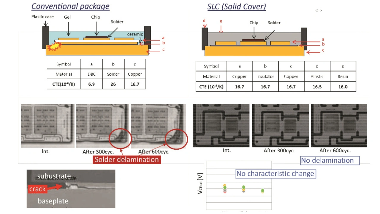
After that, Shiori Idaka from Mitsubishi Electric spoke about epoxy resin encapsulation for power modules. In addition to the classic encapsulation with silicone gel and transfer mold, this process has been recently introduced by Mitsubishi. This saves one soldering operation in the manufacturing process and only one ceramic substrate is required. Due to the simpler mechanical design, bending of the module due to different coefficients of thermal expansion can be significantly reduced, thereby reducing the mechanical stress on the module.

Even after 600 temperature cycles, no delamination was observed; whereas a conventional module showed evidence of delamination after only 300 cycles (Fig. 6; [6]). Even at low temperatures, decompression, corrosive gases and vibration, the power module encapsulated with epoxy resin proved to be superior.
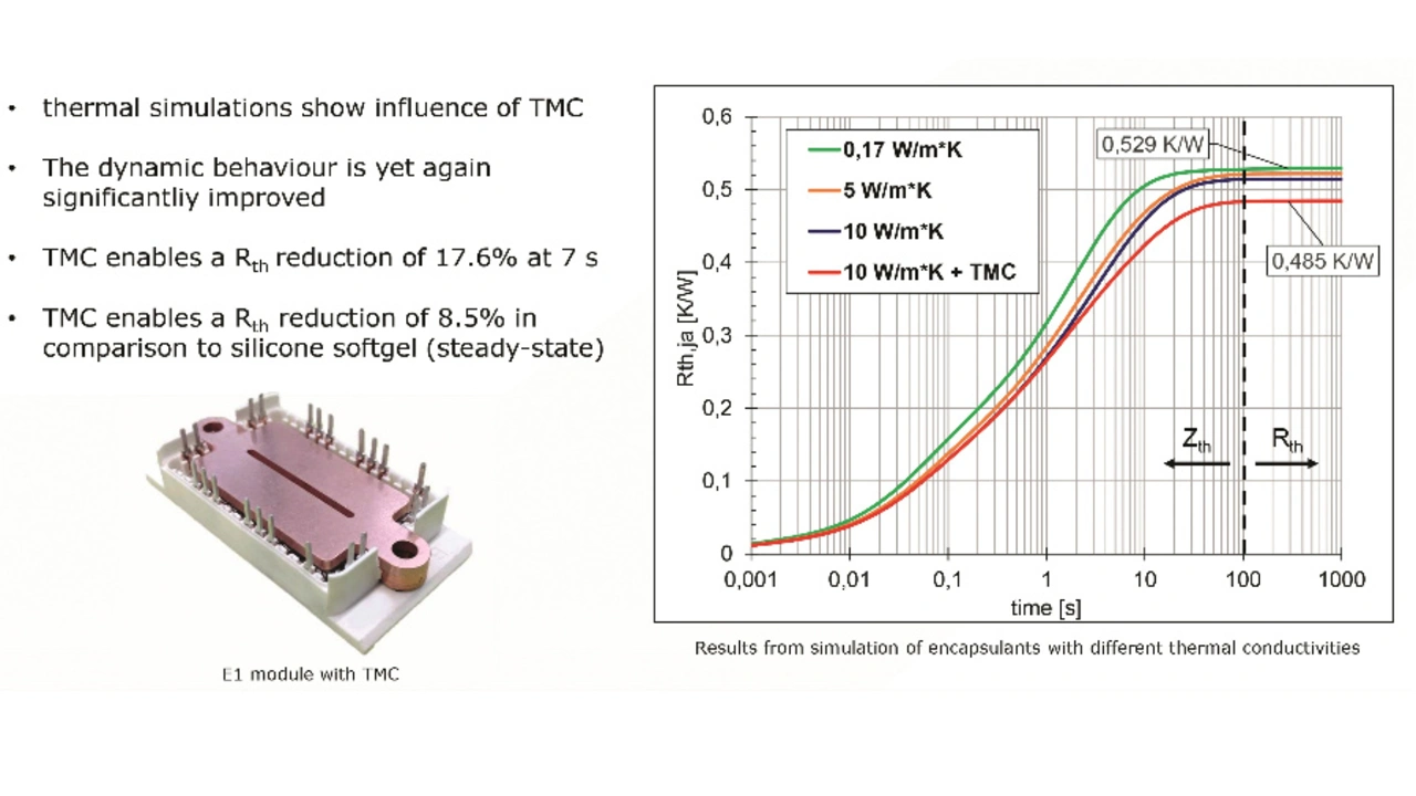
The silicone gel typically used to encapsulate a module has a very high thermal resistance and therefore does not provide an additional thermal path. Injection molded modules are better, but also more expensive. Prof. Ronald Eisele from the Kiel University of Applied Sciences presented an alternative approach. He outlined a thermal design with inorganic, i.e. ceramic encapsulation (CE). In addition, a cap made of solid copper (Thermal Mass Circuit, TMC) was added to the upper side of the module, absorbing and dissipating the heat loss (Fig. 7; [7]). As a result, the transient thermal resistance (after 7 s) was reduced by 17.6 percent compared to the standard module and by as much as 8.5 percent in steady state. At the same time, the junction temperature dropped from +128.4 °C to +115.5 °C.

Klaus Olesen from Danfoss Silicon Power dedicated not one, but two lectures to thermal management. In the first one he explained the different approaches to liquid cooling and then presented the proprietary ShowerPower technology. He highlighted various modern manufacturing processes for cooling structures which can be integrated into the base plate of a module, such as cold forging.
In his second presentation, Olesen discussed two-phase cooling. This uses the evaporation energy when the coolant changes from the liquid to the vapor state. For example, water has a specific heat capacity of 4.1 kJ/(kg∙K), but an evaporation energy of 2265 kJ/kg.

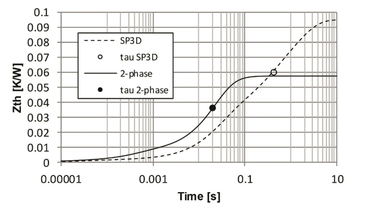
To illustrate this effect, the speaker compared two IGBT modules, a Danfoss DCM1000 module with ShowerPower3D liquid cooling and an equivalent power module with two-phase cooling. The results revealed that with two-phase cooling, the load current could increase by 60 to 70 percent while maintaining the same degree of reliability. Alternatively, the number of semiconductors in the module could be cut in half. Additionally, the thermal resistance in the steady state dropped by 40 percent and the thermal time constant from 400 ms to 20 ms (Fig. 8; [8]).
- Power Modules of the Future
- Top Side Connection of the Chip
- Encapsulation and Thermal Management
- Embedding Power Semiconductors


