Field Programmable Gate Array
Open source GateMate Integrated Logic Analyzer (ILA)
Cologne Chip provides developers with an integrated logic analyser specially developed for GateMate FPGAs, which, with its extensive range of functions, facilitates both the development of the FPGA design, known as gateware, and the implementation of the GateMate FPGA in complex systems.
The digital circuits designed specifically for FPGAs are usually developed in a hardware description language such as Verilog or VHDL and are known as gateware. The open source GateMate ILA allows you to evaluate the internal signals of your design inside the FPGA in a physical hardware setup. You can define various trigger events, ranging from simple edge detection to complex sample patterns. A flexible, user-defined duration for selected signals under test, around the configured trigger, is automatically displayed in a waveform view. This provides deep insight to better understand and optimise the functionality of complex systems.
In the real world, complex errors often go undetected in simulations. Post-implementation timing simulations are computationally intensive and may still differ from real-world conditions, especially when a digital circuit is operating close to its specification limits. External factors such as noise, temperature and unexpected peripheral events can also alter behaviour. An integrated logic analyser (ILA) is valuable for identifying such hard-to-simulate faults.
While FPGA users often have to pay expensive licensing fees to access tools and IP for their FPGAs, Cologne Chip provides an open source toolchain and continually evaluates and develops new open source gateware for the GateMate FPGA, making it freely and openly available to the community. So developers can stop wasting time on problems that have already been solved and focus on new challenges.
Components of the GateMate ILA
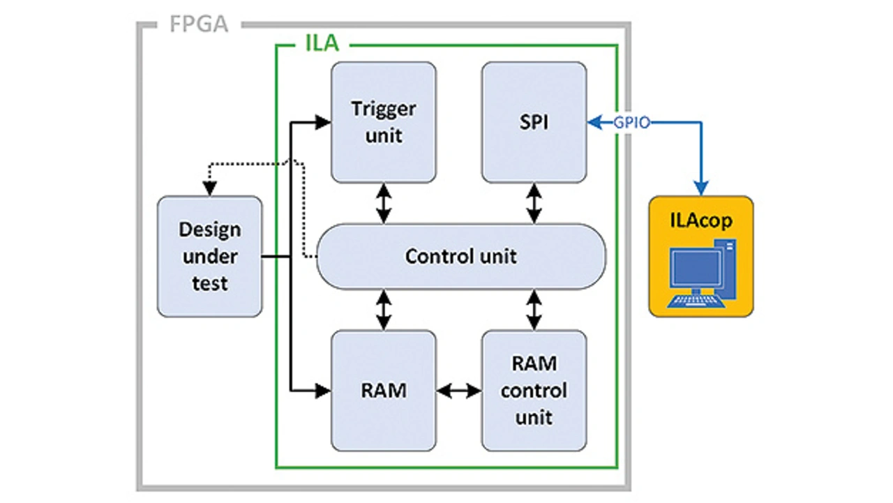
With the components shown in Figure 1, the circuit design of the ILA efficiently utilizes a minimal part of the hardware resources available in the FPGA. This allows the ILA to be configured in parallel with a resource-intensive DUT on the FPGA without affecting its normal operation.

To store a user-defined duration of a test vector at runtime, the ILA software automatically builds a cascade of internal FIFO cells. The internal Block RAM cells of the GateMate FPGA have a dedicated FIFO controller, eliminating the need for additional FPGA logic elements to implement similar functionality.
The application software known as ILAcop (ILA control program) is installed on the operating system of the user's PC and allows both the configuration of the ILA circuit design before implementation and the control of the ILA gateware at runtime via the serial peripheral interface (SPI for short). The ILAcop communicates with the ILA gateware using the same IOs that are used to configure the GateMate FPGA, so no additional hardware is required for communication.
The control unit receives commands from the user to coordinate data acquisition and to define various triggers. It also provides the ability to interact with the DUT at run time by controlling inputs or holding the DUT in a reset state.
The trigger unit implements logic to provide sample compare triggers over a large sample width (depending on the available dedicated Block RAMs), even at high frequency ranges, thanks to the implemented pipelining technique.
The resource consumption of the ILA gateware is variable due to its generic design and depends on the configuration. This includes the functions set by the user, the bit width of the test vector and the number of samples required.
FEATURES
- Setup Wizard: The user is guided through the configuration of the ILA to analyse a DUT by an intuitive and easy-to-use shell procedure that provides explanations for all configurations.
- ILA signal tagging in your source code: The ILA control program analyses your gateware design to identify signals marked with the (* ILA *) attribute, allowing them to be automatically analysed at runtime.
- No resource overflow: The ILAcop evaluates the hardware resource usage of the DUT to determine how much memory is available to store signals, ensuring that no resource overflow occurs.
- Flexible and simple selection of a sampling frequency: The sampling frequency can be a freely selectable frequency, an external clock, or a clock defined in the DUT, such as the output of an instantiated PLL.
- Parallel sampling of over 1,000 signals: The ILAcop automatically identifies all DUT signals so that the signals to be tested can be easily selected from a hierarchical list that can be filtered by module.
- Configuration of the ILA from a JSON file: All configurations created by the wizard are stored in a JSON file in plain text format. This allows the user to easily make subsequent changes, such as selecting different signals to analyse. Using the JSON file allows quick and easy configuration of the ILA.
- Trigger reconfigurable at runtime: Using the ILA's built-in communication interface, the trigger condition can be changed at any time via an interactive shell program from the user's computer, and the data acquisition process on the FPGA can be started or stopped without affecting the operation of the DUT. You can also define data acquisition sequences with different triggers. This makes it possible to record sample values for events that follow each other at short intervals. Each recording from these sequences is displayed in a separate Waveform.
- Input control and reset hold function: The ILA provides the ability to control the DUT's input signals at runtime. The reset hold function allows signals to be acquired immediately after the DUT has left the reset state.
- User defined bit patterns as triggers: The ILA allows individual trigger events to be defined. A specific bit pattern can be defined in hexadecimal or binary form to be set as the expected trigger event across the entire test vector. Each bit of the pattern can be configured as '1', '0' or 'X' (for 'don't care'). Additionally, a configurable trigger event can also be based on the rising or falling edge of a signal.
- Signal analysis via waveform: Once the defined trigger event occurs, the waveforms of the signals and signal vectors of interest can be analyzed in a viewer.

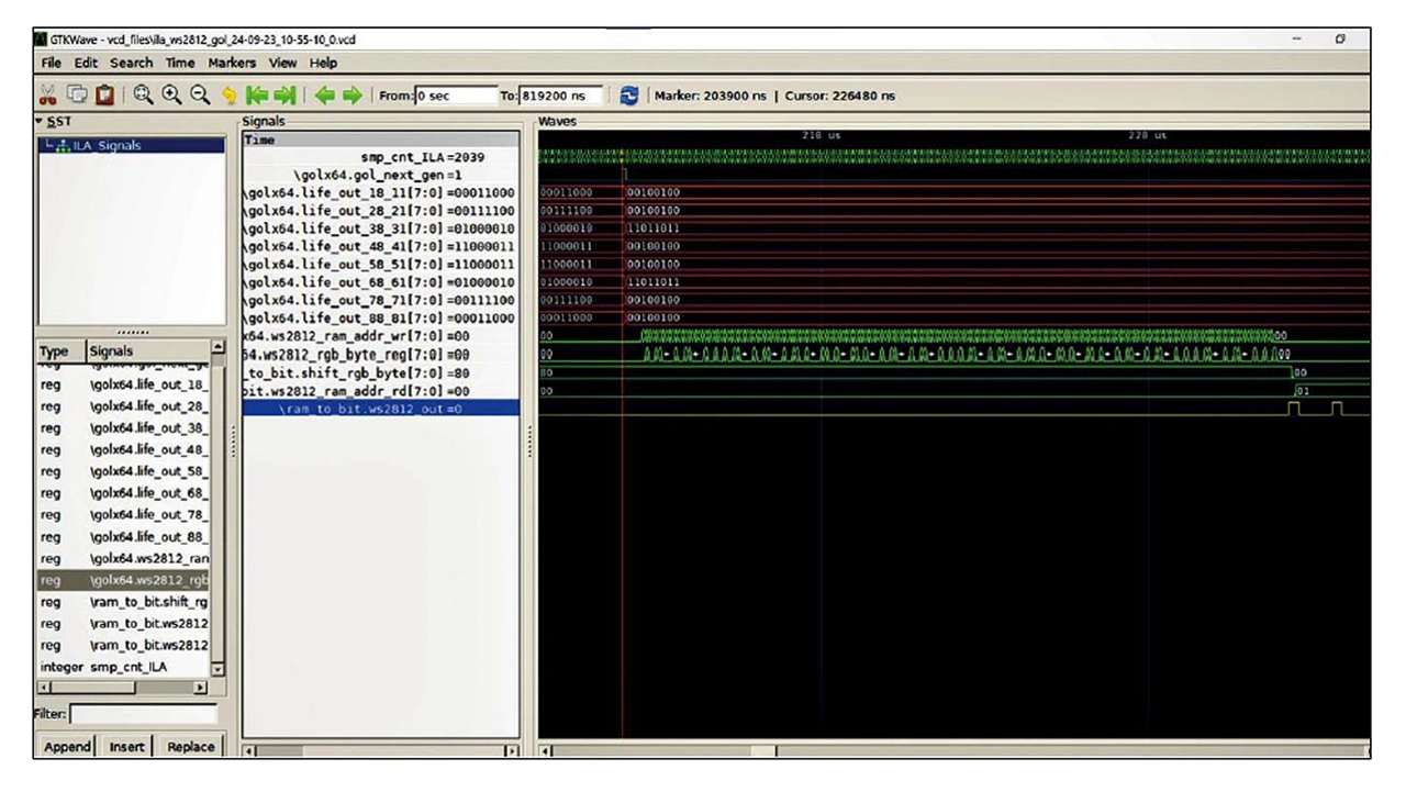
Figure 2 shows a waveform visualised by GTKWave showing the signals of a DUT from the FPGA recorded by the ILA at runtime. Alternatively, any other waveform viewer with VCD import can be used.
Conclusion
The open-source GateMate ILA offers gateware developers for GateMate FPGAs a powerful tool to thoroughly analyze the signals of their design under test in a real-world operating environment. Particularly noteworthy is the ILA's low hardware utilisation with minimal configuration, allowing it to be implemented in systems with very limited hardware resources. Its efficient design and use of pipelining techniques minimise the critical path of the ILA gateware, enabling signal analysis even at high frequency ranges.
The flexible design, developed as an open source project, is continually being enhanced with additional features. The source code of the ILA gateware and ILAcop, as well as instructions for use and installation, can be found at: https://github.com/colognechip/gatemate_ila


