Cost-effective control of rear lights
LED drivers with PWM engine and diagnostic function
The rear light is of utmost importance for road safety. However, since the space required on the electrical module is limited, several functions must be implemented using just one circuit, for example the taillight and brake light. By using ICs with an integrated PWM engine, this is made possible.
Rear lights are an important element in motor vehicles, especially for road safety: the various lighting functions of rear lights enable drivers to indicate their intentions before changing speed and direction, thus preventing dangerous situations. In addition, rear lights serve as an important distinctive and recognizable feature for the manufacturer's brand due to their striking design. However, there are limits to manufacturers' design freedom, as the unique shape of the lights means that the electrical module only offers limited space.
So, it is important to optimize not only costs but also the space required on the module, for example by implementing different functions with the same circuit while requiring only a few additional components for differentiation. Tail lamps, for instance, can be implemented as RCL (rear combination lamp). An RCL is composed of the taillight and the brake light. Although these two functions have different light intensities, they usually share the same LEDs. The taillight typically uses a light intensity that is up to ten percent lower than the brake light. To achieve the two necessary levels of light intensity, a pulse width modulation (PWM) signal is commonly used. The special thing about this is that the respective circuit can be retained for both functions.
As requirements vary depending on the OEM, there are different ways to implement an RCL. Infineon’s LITIX Basic+ TLD2252-2EP, for instance, is already equipped with a flexible, integrated PWM engine that makes it ideal for an easy and cost-effective implementation of an RCL.
Flexible PWM engine
The PWM engine operating principle of TLD2252-2EP is based on the cyclic charging and discharging of a capacitor, CPWMI, connected to the PWMI pin (Fig. 1). Charging and discharging of the CPWMI capacitor occurs with precise and constant currents. IPWM_SET and IPWM_RST are set by two resistors connected to the PWM_SET and PWM_RST pins. The currents flowing through the PWM_SET and PWM_RST pins are mirrored and sourced to the PWMI pin to charge and discharge the capacitor CPWMI with typically 1 V amplitude from 1.7 V to 2.7 V (Fig. 1).
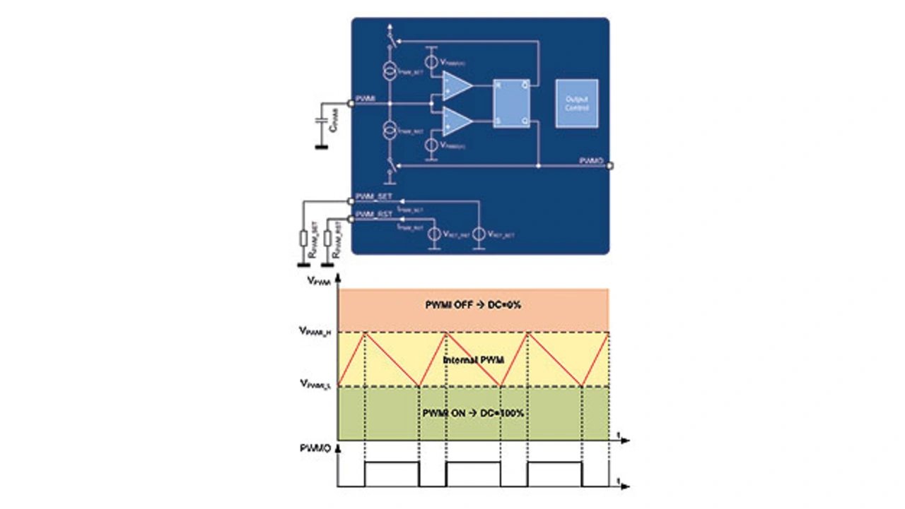
The PWM_SET and PWM_RST pins feature a fixed reference voltage, regulating at 1.22 V which is used to create two reference currents, IPWM_SET and IPWM_RST, using the RPWM_SET and RPWM_RST resistors respectively. Unique for the TLD2252-2EP is that the PWM engine is decoupled from the output control (Fig. 1). This gives more design flexibility as the two channels can be synchronized to the PWM engine individually. The PWMO pin is used to externally synchronize the two output channels. This allows only one channel to be controlled by the PWM unit. The PWM unit can even be used as a general-purpose timer engine to drive other external circuits or other LITIX Basic or LITIX Basic+ devices.
In order to synchronize the output channels, an additional feedback circuitry is needed. The signal from the PWMO pin may be fed back to the IN_SET pins, used to activate/deactivate the IN_SET current. In PWM off-time, the IN_SET is reduced to zero and in the on-time it is defined by the RSET. The feedback circuitry is either a diode and a resistor or an NPN and a resistor in case multiple drivers are driven by the PWMO signal.
The use of TLD2252-2EP to build an RCL
As part of the OEM signature, the rear light module varies in design and therefore requirements, which is why there are different ways to implement an RCL module. In most cases, the same LEDs are used for both the taillight and the brake light, even if the light intensity differs between the functions. The number of components should be kept to a minimum when implementing the functions.
The TLD2252-2EP IC reduces the number of electrical components and provides an accurate PWM engine to set two different levels of light intensity. To demonstrate this principle, an RCL module where six LEDs are used for the tail and brake lights. The light intensity for the taillight is 10 mA and for the brake light it is 50 mA. To achieve the respective light intensity level, the TLD2252-2EP uses the integrated PWM engine (Fig. 2).
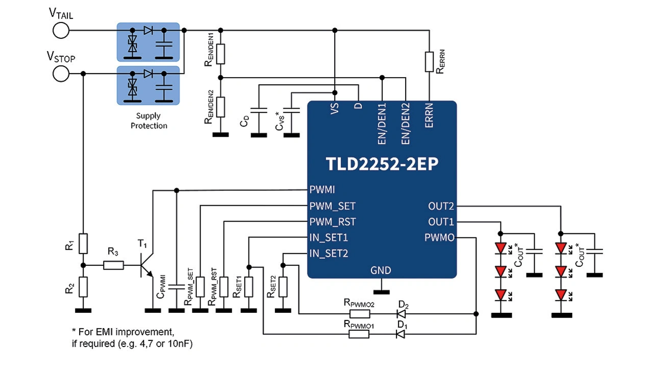
Two resistors, RSET1 and RSET2, set the output current at 50 mA on OUT1 and OUT2 channels respectively, the current level required for the brake function. The PWM engine is set via the resistors RPWM_SET, RPWM_RST and the capacitor CPWMI to 20 percent duty cycle and is active during tail operation. The two output channels are synchronized via the PWMO pin to achieve the desired light intensity.
When the brake function is active, the transistor T1 pulls the PWMI-pin to GND and deactivates the PWM engine, so that full light intensity is achieved. However, partitioning of LEDs and their light intensity can differ, according to the preference of the OEM. Light intensity could vary even within a single function. TLD2252-2EP easily implements this as it allows individual channel synchronization to the PWM signal.
For this example, six LEDs are used in a tail function with 10 mA current. During brake operation, only three LEDs increase their current to 100 mA. RSET1 sets the current of OUT1 to 10 mA while RSET2 sets the current on OUT2 at 100 mA. The PWM engine, with a duty cycle of 10 percent, is synchronized externally with OUT2. During the tail operation, only OUT2 is driven by the PWM signal, and all six LEDs have the same light intensity. During brake operation, the PWM engine is deactivated, transistor T1 pulls the PWMI pin to GND, and the LEDs on OUT2 are driven with full light intensity at 100 mA.
TLD2252-2EP offers another advantage when used in a module. The IC can drive other LITIX Basic+ devices with a PWM signal, even when TLD2252-2EP channels do not need any PWM (Fig. 3). In this example, a total of nine LEDs form an RCL module. All of them are driven by a 50 mA current during tail operation. However, only three LEDs are driven by a 200 mA current when the brake operation is active.
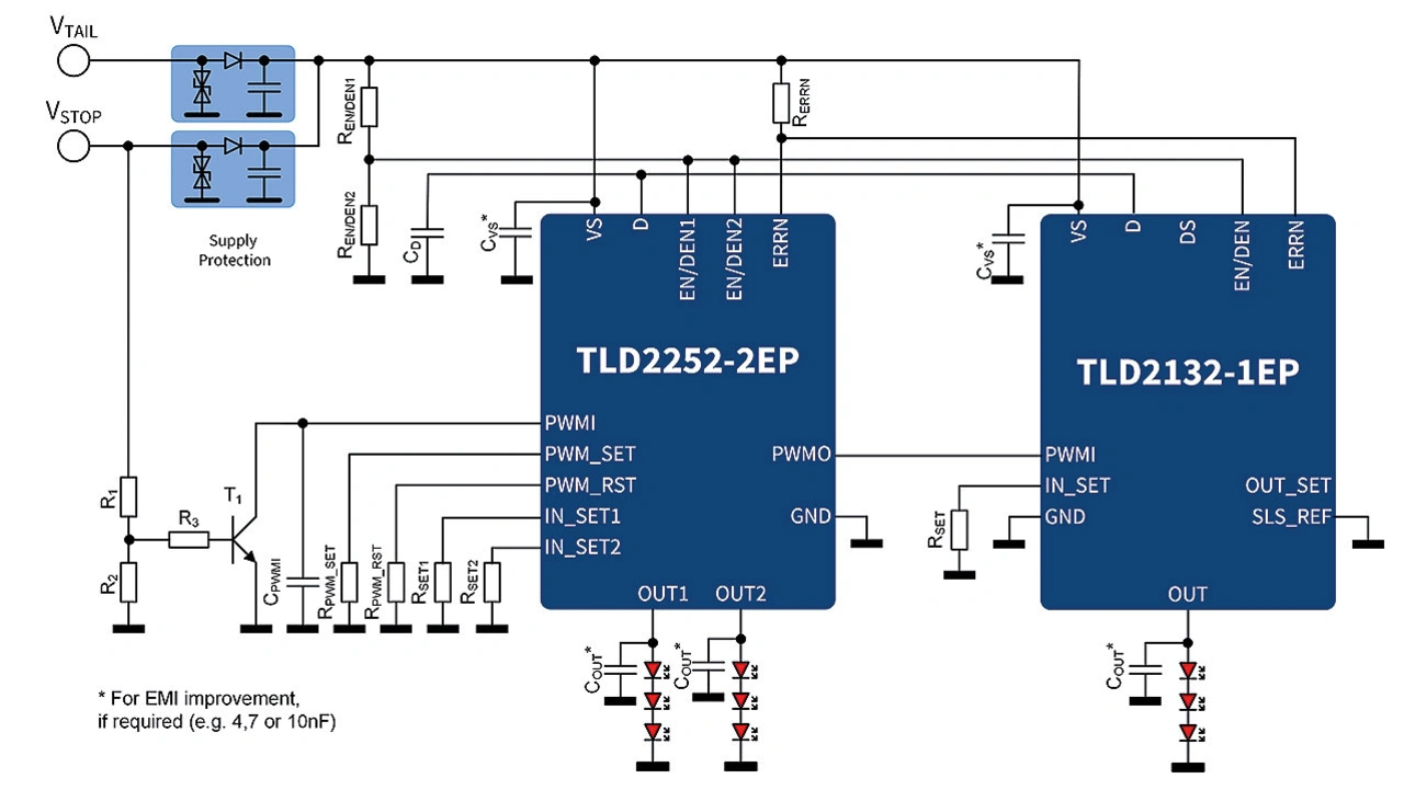
To implement this module, a TLD2252-2EP and a TLD2132-1EP are combined, with each output channel driving a string of three LEDs. The RSET1 and RSET2 resistors are used to set the output current of OUT1 and OUT2 respectively to 50 mA. RSET resistor sets the output current of TLD2132-1EP OUT to 200 mA. The TLD2252-2EP PWM engine is configured with a duty cycle of 25 percent. Additionally, the PWMO pin synchronizes with the TLD2132-1EP. When the tail operation is active, only the OUT channel of TLD2132-1EP is driven by the PWM signal. The two TLD2252-2EP channels are not externally synchronized with the PWM signal.
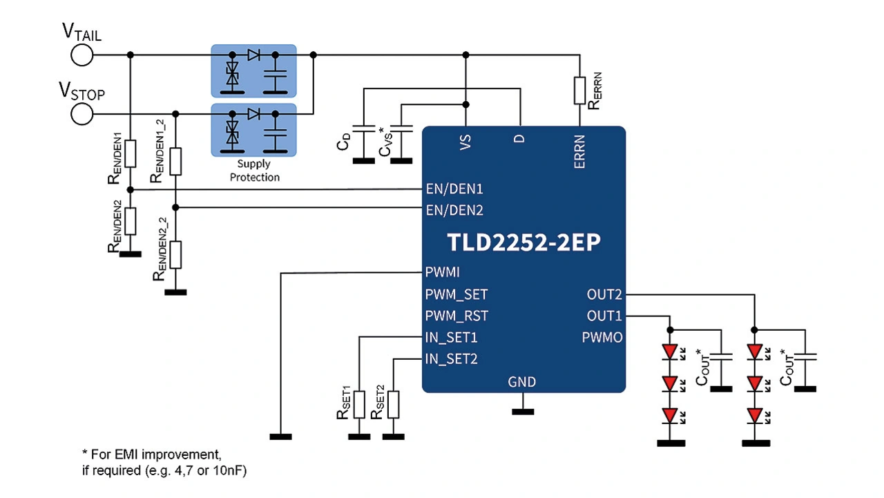
In addition to the flexible PWM engine, the TLD2252-2EP offers another feature to ease the design. Each output channel can be activated individually via dedicated enable pins. This allows more freedom for design, as each channel can be used for different LED functions.
This further reduces the total count of components in the rear light module and minimizes the overall PCB space. A simple example of a tail and brake function, where each function uses dedicated LEDs, shows the benefits from individual activation of the two channels. Here, each function utilizes three LEDs. Only one TLD2252-2EP is used to implement both functions and optimizes the required BOM (bill of material) (Fig. 4).
The TLD2252-2EP is well-suited to many OEM requirements in rear lighting. Its flexible PWM engine gives designers the freedom to build their desired rear light modules. Both channels of the TLD2252-2EP can be activated individually which allows usage either for two separate lamp functions or a rear combination lamp and can address most of the OEM requirements worldwide. With the TLD2252-2EP, one can minimize design-in efforts and produce a cost-effective rear lamp.
The authors

Vasiliki Makantasi
is an application engineer at Infineon Technologies responsible for automotive LED drivers. She studied Electronic and Embedded Computing Systems Engineering at both TEI and the University of Piraeus.

Volker Taggruber
is Senior Product Manager for automotive LED drivers for front and rear light applications at Infineon Technologies. He studied physics at the University of Regensburg and at the University of Illinois at Urbana-Champaign.
